2-channel input module for current / voltage Part B VC-6000
TM
Compact monitor
© VC-6000
TM
Compact monitor Nov, 2014 C100584.002 Module Vers. 08 - 31 -
5.2.2 Equipment and signalling
♦ Possible socket positions on the Base Module X1_M X2_M X3_M
♦ Connection plugs on the Base Module X1 X2 X3
♦ Connection plug layout of a GP-TIM
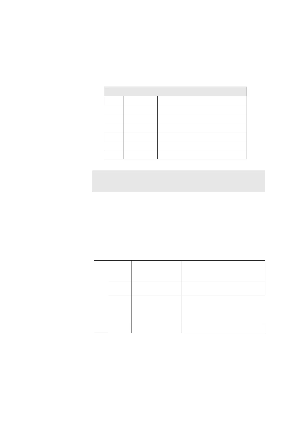
GP-TIM Pin layout connections X1/X2/X3
PIN Signal Explanation
1 Volt in A Voltage input, channel A
2 Curr in A Current input, channel A
3 COM A Reference potential, channel A
4 Volt in B Voltage input, channel B
5 Curr B Current input, channel B
6 COM B Reference potential, channel B
Note:
Either two current inputs or two voltage inputs can be used at one
GP-TIM. A mixture of these input signal types is not possible !
♦ OK-LED (GN)
The green LED signals the OK status of the sensor. If there is an OK-
fault the LED will be extinguished. The OK monitoring checks the
status of the sensor signal (including the DC value) with reference to the
OK-voltage window. This OK-window (upper and lower limits) can be set
up using the User Terminal.
An OK-fault exists as soon as a single sampled value is found to lie
outside the set OK-window range.
OK-LED
Green Off Continuous sensor OK fault
exists; has been confirmed
through the dialogue
Green Flashing at 2 Hz Sensor OK fault exists; not yet
confirmed through the dialogue
Green Flashing at 0,5 Hz Only with OK latching:
No OK fault currently exists; an
earlier fault not yet confirmed
through the dialogue
Green On No sensor OK fault