VC-6000
TM
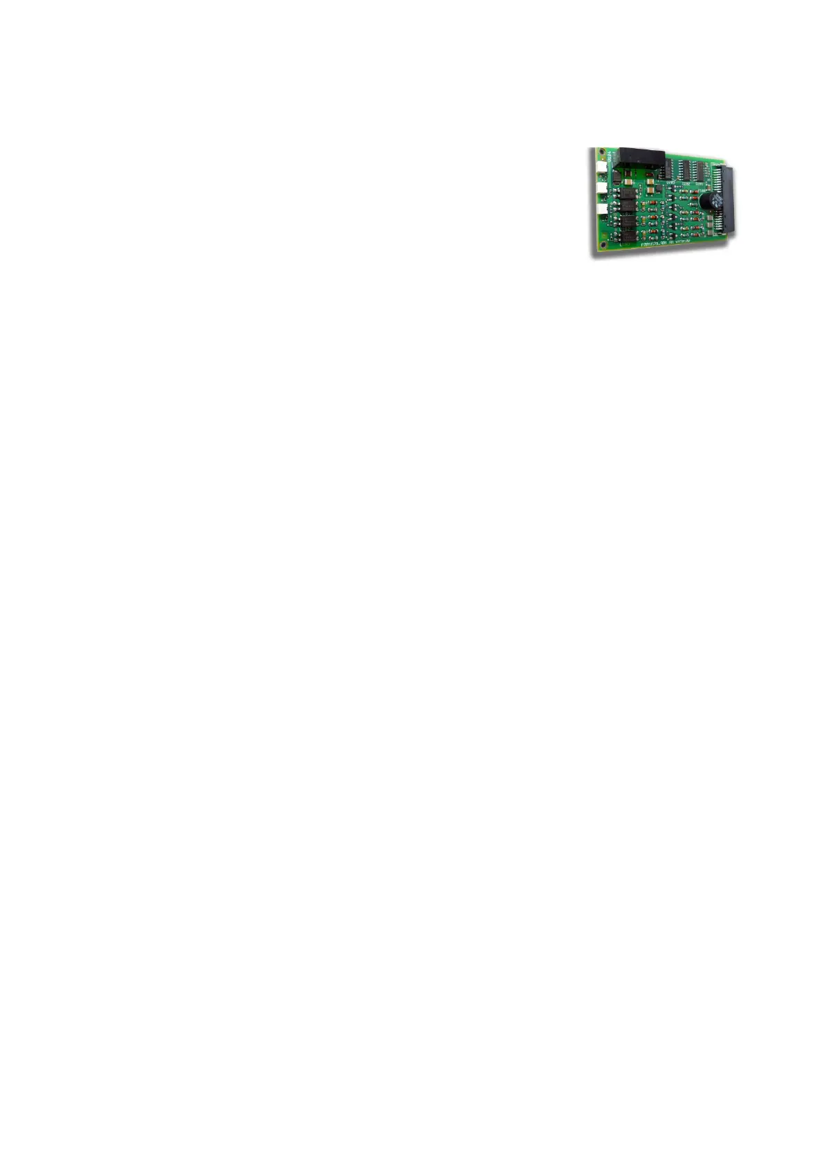
Compact monitor Part B 3-channel input module for binary status signals
- 34 - C100584.002 Module Vers. 08 © VC-6000
TM
Compact monitor Nov. 2014
7 3-channel input module for binary
status signals
7.1 Function
♦ The input module for binary status signals,
abbreviated to BINARY-IN, is laid out for a
maximum of 3 input signals.
♦ Each BINARY-IN module is laid out to process either
1. non-active signals from external potential-free contacts,
2. active signals from external current sources (e.g. PNP open-
collector) or
3. active signals from external current sinks (e.g. NPN open-collector).
With non-active signals the required auxiliary power is prepared by
the BINARY-IN module.
Active and non-active signals may not be simultaneously fed to the
same module because the switching of the auxiliary voltage is not done
separately to the channels.
♦ Each input channel of the BINARY-IN module is managed internally in
the instrument through a binary block (firmware), i.e. a BINARY-IN input
channel and a binary block together form a physical interface to the
outside world for the VIBROCONTROL 6000 Compact monitor. The
connected input signal is acquired and made available to the successive
signal path for further processing and assessment, e.g. switching the
Trip Multiply function on and off.
♦ The current logical state (ON or OFF) of each input channel is
displayed respectively by a yellow LED.
7.2 Technical data
7.2.1 Electrical properties
Input:
General properties galvanically-separate, polarized
Input impedance 3 kΩ
Maximum contact voltage 50 V
Minimum current load for potential-free contacts 5 mA
Accuracy 5 ms
Signal status LOW:
Nominal input voltage 0 V DC
Input voltage range -50 V...+ 5,0 V DC
Maximum input current 1 mA
Signal status HIGH:
Nominal input voltage + 24 V DC
Input voltage range + 16,5 V...+ 50 V DC
Minimum input current 5 mA