3-channel input module for binary status signals Part B VC-6000
TM
Compact monitor
© VC-6000
TM
Compact monitor Nov, 2014 C100584.002 Module Vers. 08 - 35 -
7.2.2 Equipment and signalling
♦ Possible socket positions on the Base module X1_M to X9_M
♦ Connection plugs on the Base module X1 to X9
♦ Connection plug layout with BINARY-IN equipment
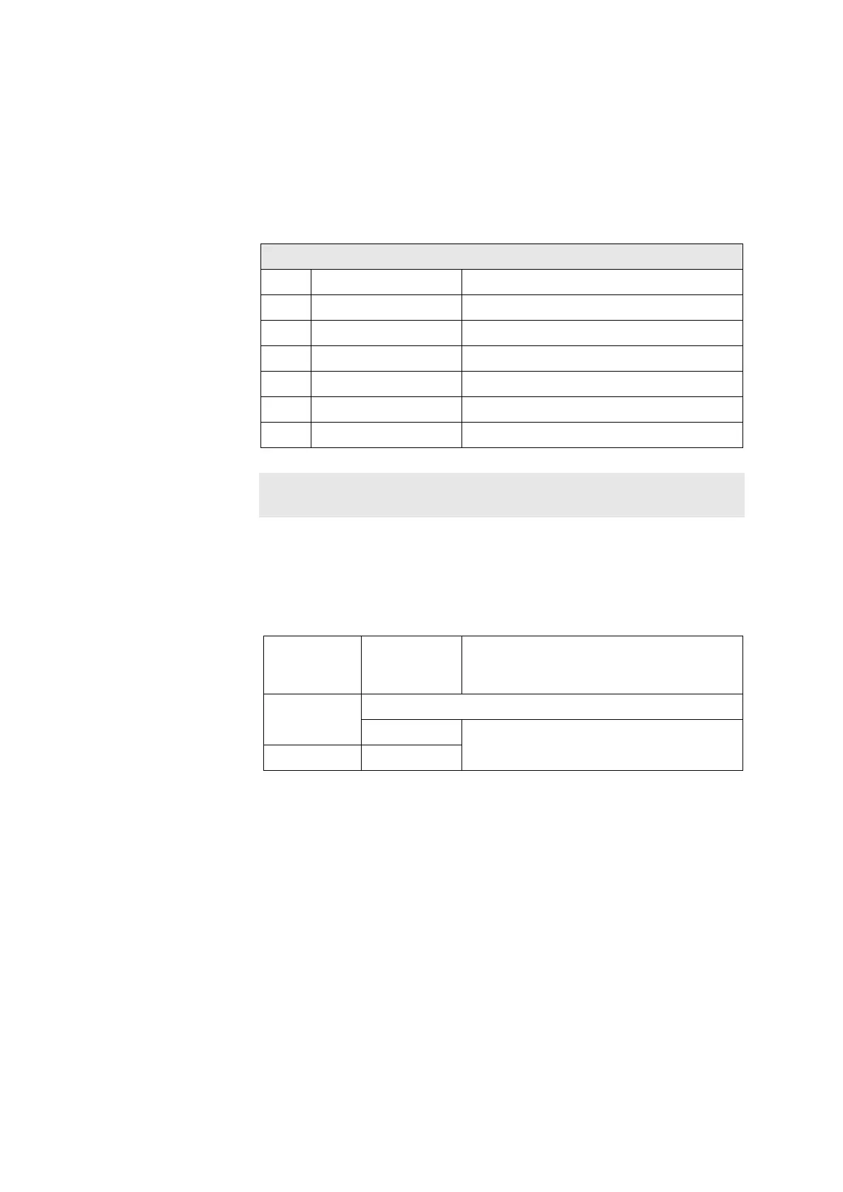
BINARY-IN Connection pin layout X4 to X9
PIN Signal Explanation
1 HI A Channel A input HIGH
2 LO A Channel A input LOW
3 HI B Channel B input HIGH
4 LO B Chanel B input LOW
5 HI C Channel C input HIGH
6 LO C Channel C input LOW
Note:
The inputs A,B,C are not separated galvanically
♦ Status LED (yellow)
The yellow LEDs signal the current logical evaluated state of the
respective assigned channel.
Status
LED
(yellow)
Logical
state
Input signal
Off Undefined channels are not evaluated
OFF Dependent upon the parameter „Active
State“, see Binary block for details
On ON