VC-6000
TM
Compact monitor Part B 2-channel Relay output module
- 40 - C100584.002 Module Vers. 08 © VC-6000
TM
Compact monitor Nov. 2014
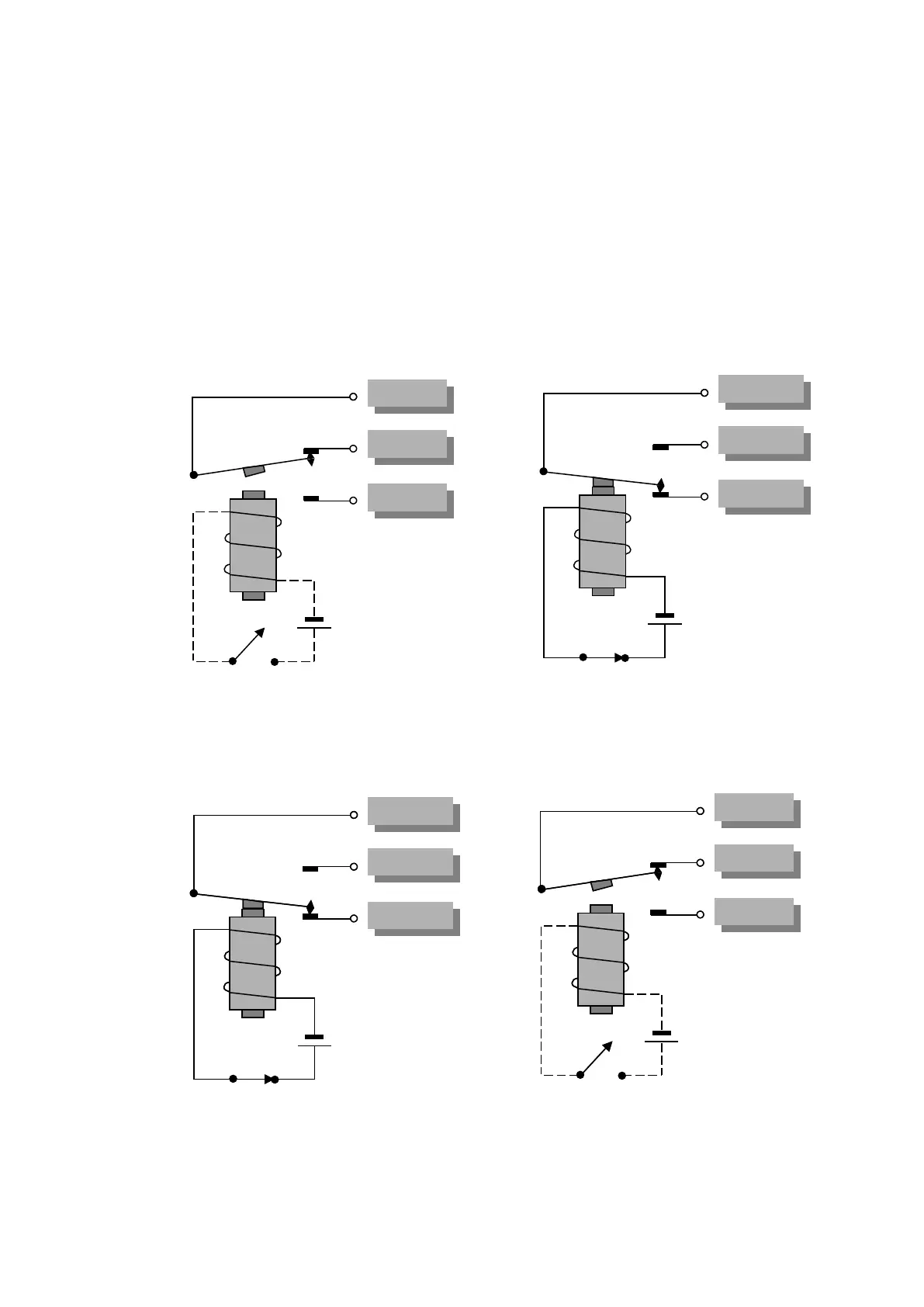
8.3 Wiring of relay outputs
8.3.1 Relay switch mode
When connnecting the relay contact it should be noted that the relay outputs
can be operated selectively as normally de-energised or normally energised
relays (see figure for details)
Pins no. 1-3 are referred to channel A, and pins no. 4-6 to channel B.
Principle diagram for normally de-energised switching:
Normal position Position after an event signal
Principle diagram for normally energised switching:
Normal position Position after an event signal
Pin 1 (4)
Pin 1 (4)
Pin 3 (6)
Pin 3 (6)
Pin 2 (5)
Pin 2 (5)
Pin 1 (4)
Pin 1 (4)
Pin 3 (6)
Pin 3 (6)
Pin 2 (5)
Pin 2 (5)
Pin 1 (4)
Pin 1 (4)
Pin 3 (6)
Pin 3 (6)
Pin 2 (5)
Pin 2 (5)
Pin 1 (4)
Pin 1 (4)
Pin 3 (6)
Pin 3 (6)
Pin 2 (5)
Pin 2 (5)
Pin 1 (4)
Pin 1 (4)
Pin 3 (6)
Pin 3 (6)
Pin 2 (5)
Pin 2 (5)
Pin 1 (4)
Pin 1 (4)
Pin 3 (6)
Pin 3 (6)
Pin 2 (5)
Pin 2 (5)