Modular Fire Panel Installation | en 129
Bosch Sicherheitssysteme GmbH System Description F.01U.028.089 | 8.0 | 2011.07
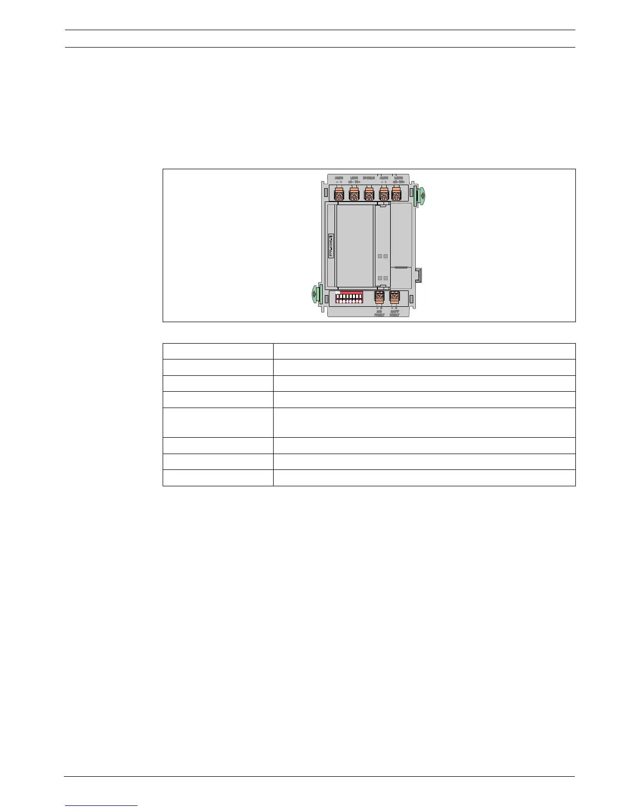
FPP-5000-TI Trouble Interface
The FPP-5000-TI module is used in the FPP-5000 External Power Supply Unit with the BCM-
0000-B to transmit faults to the fire panel via the Local Security Network (LSN).
Two independent signal inputs for "battery fault" and "mains current fault" allow a specified
fault indication on the fire panel.
The FPP-5000-TI is connected directly to the LSN bus line and supplied with power via the bus
line.
Figure 4.84 FPP-5000-TI Trouble Interface
You can find the installation instructions for the FPP-5000-TI module at
www.boschsecurity.com (document number for installation instructions: F.01U.081.396).
The technical data can be found in Section 7.6.2 FPP-5000-TI Trouble Interface, page 165.
Labeling Connection
AUX1 - | AUX1 + Auxiliary power supply, incoming
LSN1 a1 - | LSN1 b1 + LSN in
SHIELD Shield wire
AUX2 - | AUX2 + Auxiliary power supply, outgoing
(support points for looping through)
LSN1 a2 - | LSN1 b2 + LSN outgoing
AC FAULT - | + Input of mains fault
BATT FAULT - | + Input of battery fault

 Loading...


