172 en | Modular Fire Panel
F.01U.028.089 | 8.0 | 2011.07 System Description Bosch Sicherheitssysteme GmbH
A.3 Special Applications
A.3.1 Controlling Extinguishing Systems
The FPA enables the activation of extinguishing systems via the extinguishing interface
described in VDE 0833 Part 2 or by the VdS (standard interface SST in line with VdS Guideline
2496). Connection occurs either at the panel using the RMH 0002 A Relay Module for mains
power or in the field via the FLM-420-RLE Interface Module.
For each panel, a maximum of 8 extinguishing panels can be activated in each case via an
RMH 0002 A Relay Module for mains power. For each LSN loop, a maximum of 8 extinguishing
systems can be activated in each case via an FLM-420-RLE Interface Module.
The requirement is for a maximum of one extinguishing area to fail in the case of a system
fault. This means that from the second extinguishing area, there must be a redundant MPC
panel controller.
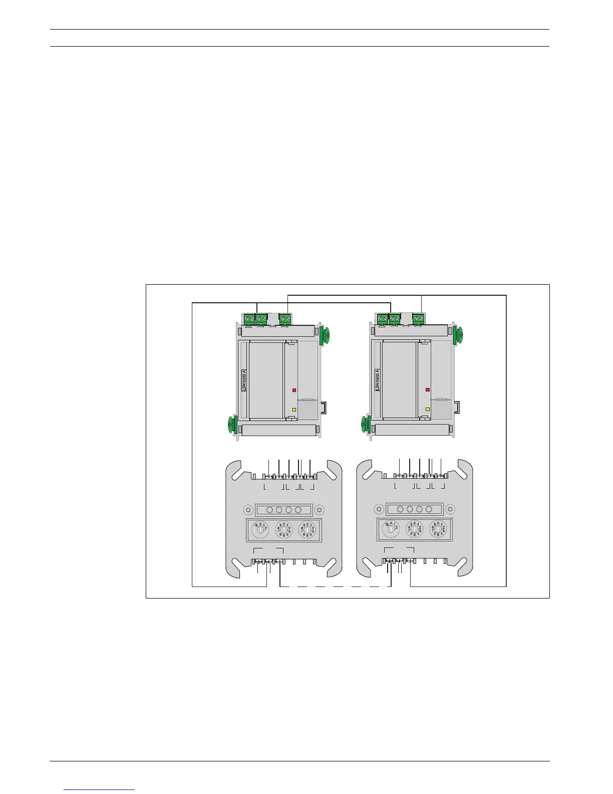
If several FLM-420-RLE Interface Modules are used to control the extinguishing system in each
LSN loop, in addition to the redundant panel controller, the associated LSN 0300 A or
LSN 1500 A module must also be duplicated.
Figure 1.1 Several FLM-420-RLE modules in the LSN loop
LSN 0300 A
AUX1 LSN1 AUX2 LSN2
+ – a– b+ + – a– b+
b1+ a- b2+
LSN
REL1
FB2
FB1
NO
COM
–
+
+
FLM-420-RLE-S
LSN 0300 A
AUX1 LSN1 AUX2 LSN2
+ – a– b+ + – a– b+
b1+ a- b2+
LSN
REL1
FB2
FB1
NO
COM
–
+
+
FLM-420-RLE-S

 Loading...


