164 en | Technical Data Modular Fire Panel
F.01U.028.089 | 8.0 | 2011.07 System Description Bosch Sicherheitssysteme GmbH
Installation of the power supply unit is described in Section 4.9.12 NZM 0002 A Notification
Appliance Zone Module, page 122.
7.5.12 RMH 0002 A Relay Module for mains voltage
Installation of the power supply unit is described in Section 4.9.13 RMH 0002 A Relay Module
for Mains Voltage, page 123.
7.5.13 RML 0008 A Relay Module for Low Voltage
Installation of the power supply unit is described in Section 4.9.14 RML 0008 A Relay Module
for Low Voltage, page 124.
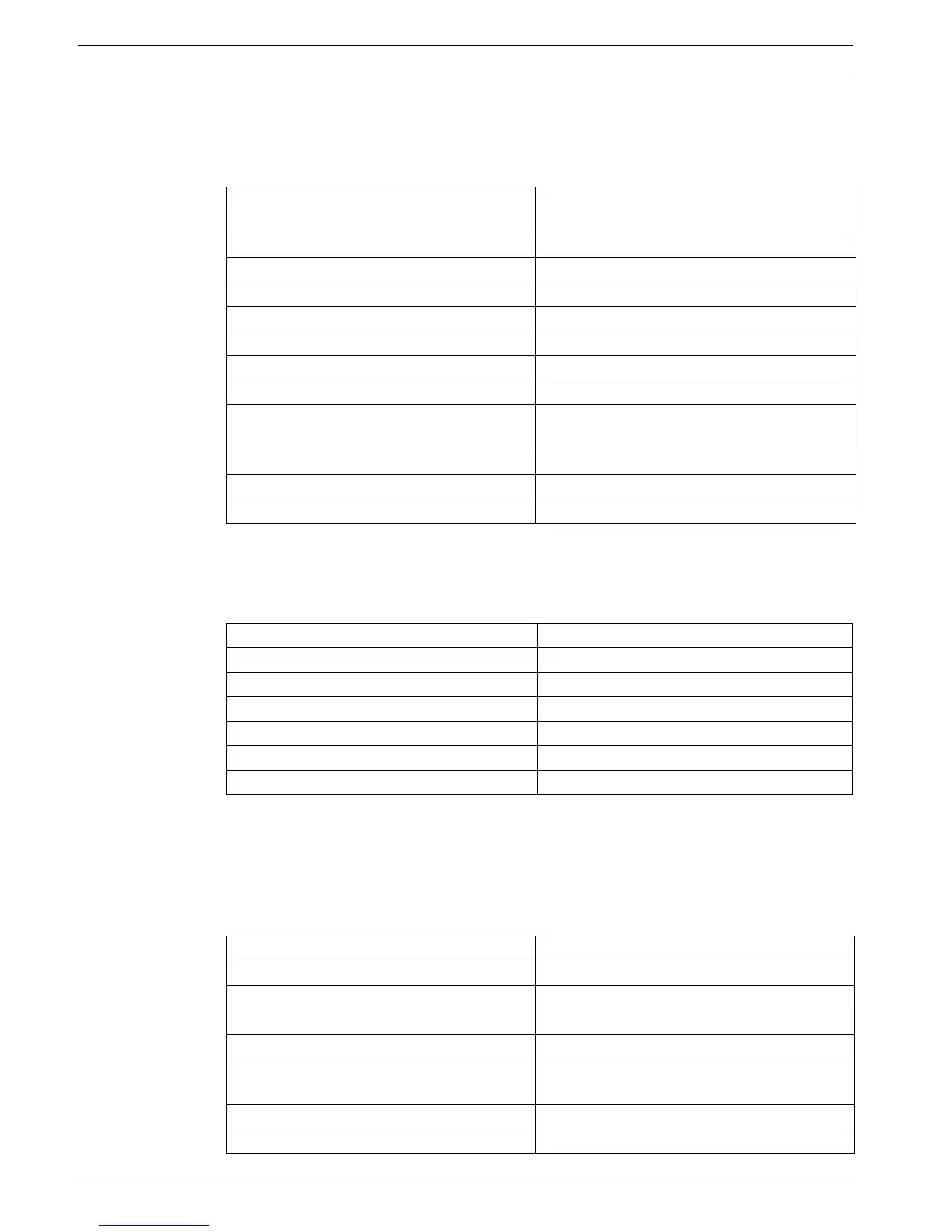
7.6 FPP-5000 External Power Supply Unit Kit 24 V/6 A
7.6.1 FPP-5000 Kit
Operating and display elements 4 LEDs (2 x red, alarm/2 x yellow, fault)
2 buttons (each on/off)
Fuses F1 = T 6.3 A, F2 = T 6.3 A
Input voltage 20 V DC to 30 V DC/5 V DC ± 5 %
Feedback current max. 8.5 mA per feedback output
Feedback voltage max. 30 V DC
Maximum current consumption
– Standby operation 10 mA
– Both relays tripped 50 mA
Maximum contact load 5 A at 120 V/230 V AC or 5 A at 30 V DC
(resistive)
Maximum line resistance of feedback lines 2 x 25 Ω
Space required (H x W x D) approx. 127 x 96 x 60 mm
Weight Approx. 135 g
Input voltage 20 V DC to 30 V DC/5 V DC ± 5 %
Maximum current consumption
– Standby operation 4 mA
– All relays tripped 68 mA
Maximum contact load 1 A at 30 V DC resistive
Space required (H x W x D) approx. 127 x 96 x 60 mm
Weight approx. 150 g
Input voltage range 100 V AC to 240 V AC
Input frequency range 50 Hz to 60 Hz
Efficiency > 85 %
Back-up time >100 ms at 230 V AC
Output voltage
– With mains supply 26 - 29 V DC (depending on temperature),
26.8 V DC nominal (at 40 °C)
– With battery supply 21 - 23 V DC
Maximum output current 6 A

 Loading...


