Modular Fire Panel Technical Data | en 161
Bosch Sicherheitssysteme GmbH System Description F.01U.028.089 | 8.0 | 2011.07
7.5.4 ENO 0000 B Fire Service Interface Module
Installation of the power supply unit is described in Section 4.9.5 ENO 0000 B Fire Service
Interface Module, page 114.
7.5.5 FPE-5000-UGM Interface Module
Installation of the power supply unit is described in Section 4.9.6 FPE-5000-UGM Interface
Module, page 115.
7.5.6 IOP 0008 A Input/Output Module
Installation of the power supply unit is described in Section 4.9.7 IOP 0008 A Input/Output
Module, page 116.
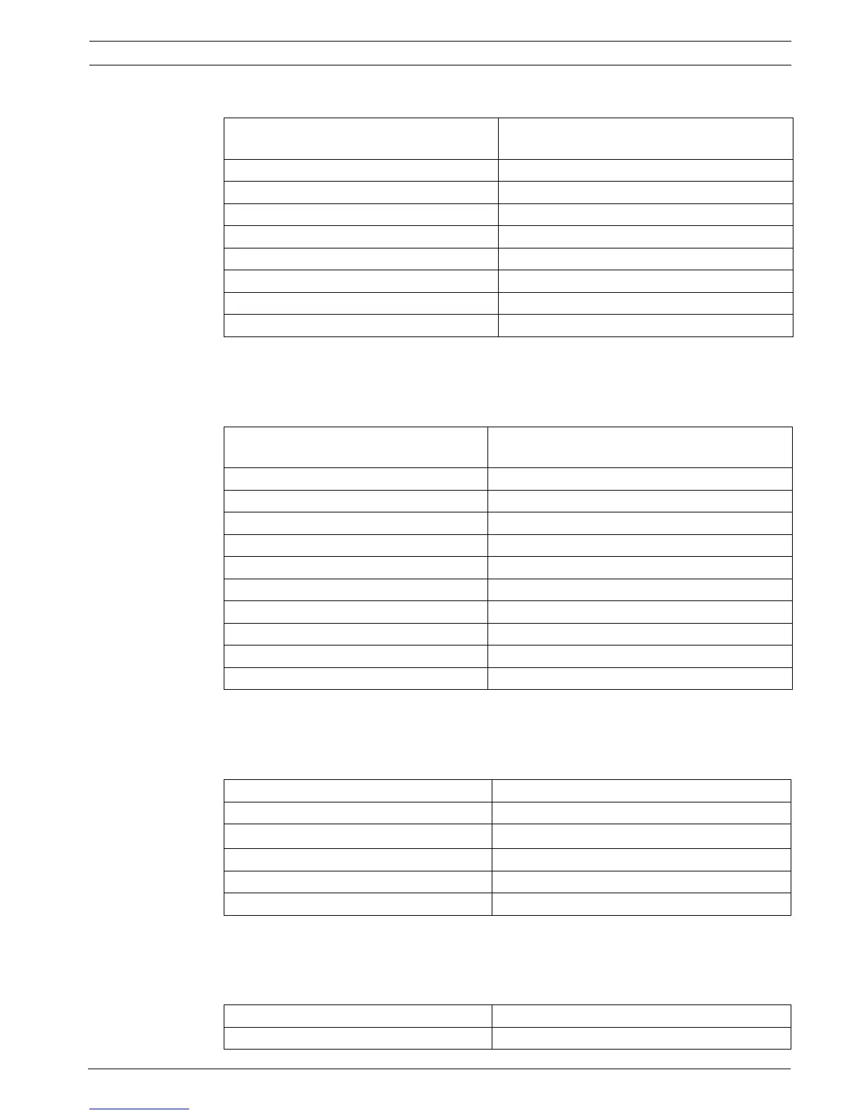
7.5.7 IOS 0020 A 20 mA Communication Module
Operating and display elements 2 LEDs (1 x red, 1 x yellow)/1 button (LED
test)
Input voltage 20 V DC to 30 V DC
Current consumption
–In standby 25mA
– All relays tripped 60 mA
– Key deposit heating additional 240 mA
Permissible relay contact load 1 A/30 V
Space required (H x W x D) approx. 127 x 96 x 60 mm
Weight approx. 150 g
Operating and display elements 4 two color LEDs (green = transmission / yellow
= fault), 1 button (LED test)
Input voltage 20 V DC to 30 V DC/5 V DC ± 5 %
Maximum cable length 1000 m
Maximum line resistance 70 Ω
Transmission rate 9600 bit/s at 1000 m to 38400 bit/s at 200 m
Maximum current consumption
– Standby operation 7 mA (at 24 V)
– One transmission path active 10 mA (at 24 V)
– Both transmission paths active 13 mA (at 24 V)
Space required (H x W x D) approx. 110 x 90 x 60 mm
Weight approx. 150 g
Input voltage 20 V DC to 30 V DC/5 V DC ± 5 %
Maximum current consumption 10 mA at 5 V DC
Maximum switch-on current 700 mA (short-circuit protected, I
max
= 1.5 A)
Maximum cable length 3 m
Space required (H x W x D) approx. 127 x 96 x 60 mm
Weight approx. 150 g
Input voltage 20 V DC to 30 V DC/5 V DC ± 5 %
Maximum current consumption 15 mA at 24 V DC

 Loading...


