Modular Fire Panel Planning | en 33
Bosch Sicherheitssysteme GmbH System Description F.01U.028.089 | 8.0 | 2011.07
3.5 Addressing
LSN elements are addressed via rotary switches (e.g. FAP 420) or DIP switches (e.g. E/W
versions of the FLM-420).
For the detectors, there are three rotary switches on the underside, which can be used to
select automatic or manual addressing with or without automatic detection.
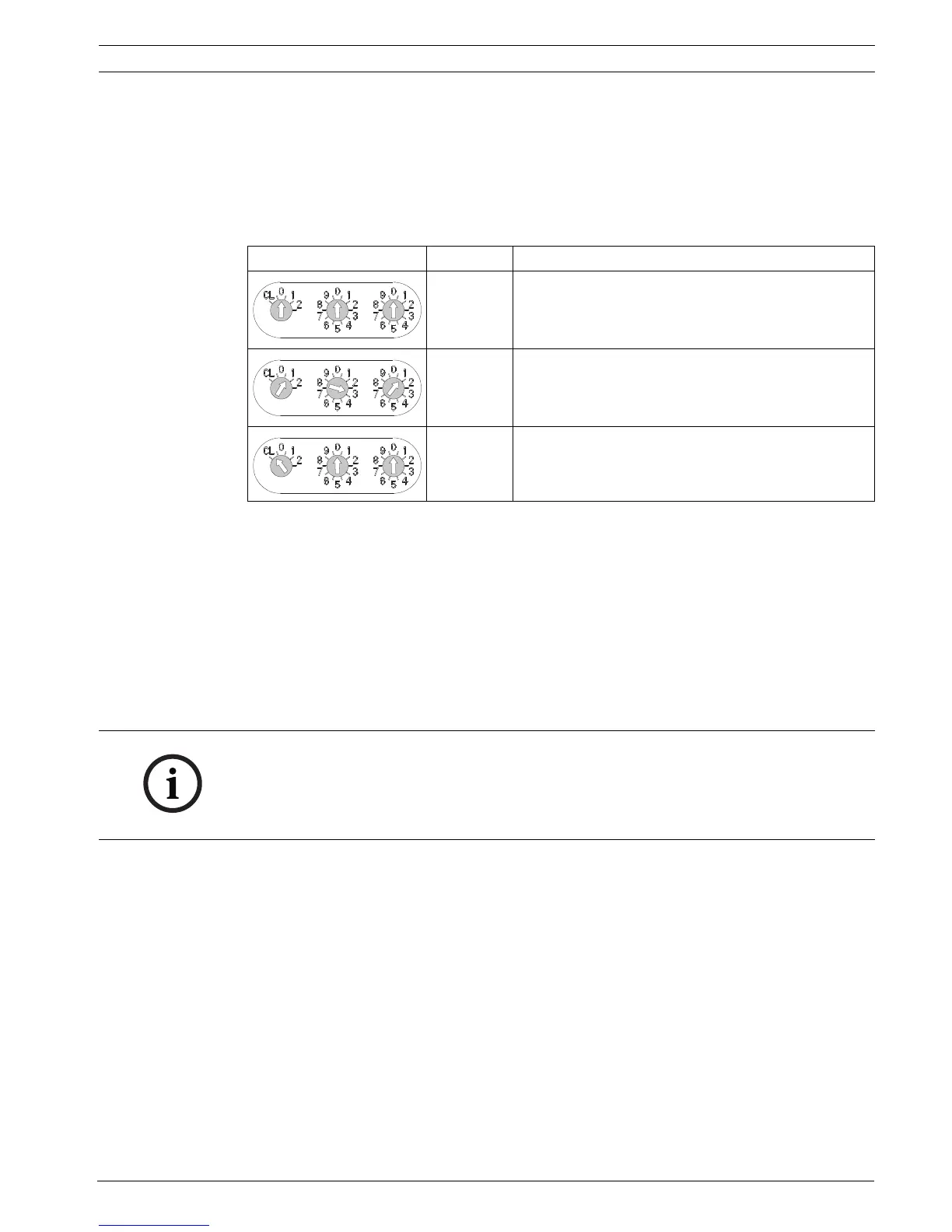
The following settings are possible:
Table 3.4 Addressing via rotary switches
The rotary switches are moved to the required position using a slotted-head screwdriver.
Automatic Addressing
If addresses are automatically allocated by a fire panel with LSN improved version technology,
all detectors must have the address "0 0 0" (factory default setting).
Manual Addressing
With manual addressing, the detector address is set using the three rotary switches. The
right-hand rotary switch is used to set the units, the central rotary switch is used to set the
tens and the left-hand rotary switch is used to set the hundreds.
From the LSN module software version 1.0.35 onwards, you can operate LSN improved
elements and LSN classic elements in combination in a loop or stub. If an LSN classic element
is present, only 127 elements can be used in the loop.
Note that structures with T-tapping are only possible if only LSN improved elements are used
(see Section 3.3 Structures in Local Security Network, page 31).
For setting addresses with DIP switches, refer to the instructions in the installation guide
supplied with the products.
Rotary switch setting Address Operating mode
0 0 0 Loop/stub in LSN improved version mode with
automatic addressing (T-tapping not possible) =
factory default setting
0 0 1
...
2 5 4
Loop/stub/T-tapping in LSN improved version mode
with manual addressing (address shown in
example = 131)
CL 0 0 Loop/stub in LSN classic mode with automatic
addressing (T-tapping not possible, maximum
number of elements = 127)
NOTICE!
Using addresses greater than 254 is not permitted.
This will prompt the display of an error message on the fire panel.
With manual addressing, all the detectors in a loop, stub or T-tap must have an address
between 1 and 254.

 Loading...


