52 en | Installation Modular Fire Panel
F.01U.028.089 | 8.0 | 2011.07 System Description Bosch Sicherheitssysteme GmbH
4.3 Installation of Housing Components
Installation Instructions for Wall Mounting Housing and Mounting Frame
All listed mounting frames, wall mounting housings, and extension housings are supplied with
the following installation materials:
– 3 6 x 50 mm screws
– 3 Ø 8 mm dowels
To install, proceed as follows:
1. Mark the 3 required holes on the wall as shown in the installation drawing.
2. At the marked points, drill holes approx. 55 mm deep with an 8-mm drill. Insert a dowel
in each hole.
3. Screw the upper fixing screws to a distance of 5 mm from the wall and fit the housing or
mounting frame.
4. Now fit the third fixing screw. This 'safety' screw prevents the housing from being pushed
up and off the top screws.
5. Then check the installation position and securely tighten all screws.
Installing Several Housings
It is possible to install several housings for frame mounting directly beneath each other by
connecting the frames to each other. The following instructions explain such an installation
using the example of the FBH 0000 A and FSH 0000 A mounting frames.
First, install the FBH 0000 A mounting frame as explained above (steps 1–5).
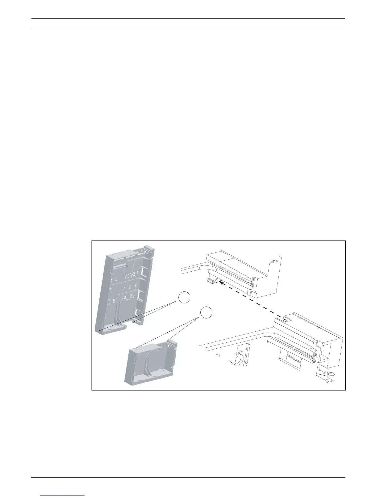
6. Push the grooves of the FSH 0000 A Mounting Frame (2) onto the guide rails of the
FBH 0000 A Mounting Frame (1).
Figure 4.1
7. Mark the 3 required holes on the wall as shown in the installation drawing for the
FSH 0000 A Mounting Frame (see Figure 4.13, Page 65).
8. Remove the FSH 0000 A Mounting Frame.
9. At the marked points, drill holes approx. 55 mm deep with an 8-mm drill. Insert a dowel
in each hole.
10. Refit the FSH 0000 A Mounting Frame, as described in step 6.
11. Screw the FSH 0000 A Mounting Frame tight.
1
2
FBH 0000 A
FSH 0000 A

 Loading...


