110 en | Installation Modular Fire Panel
F.01U.028.089 | 8.0 | 2011.07 System Description Bosch Sicherheitssysteme GmbH
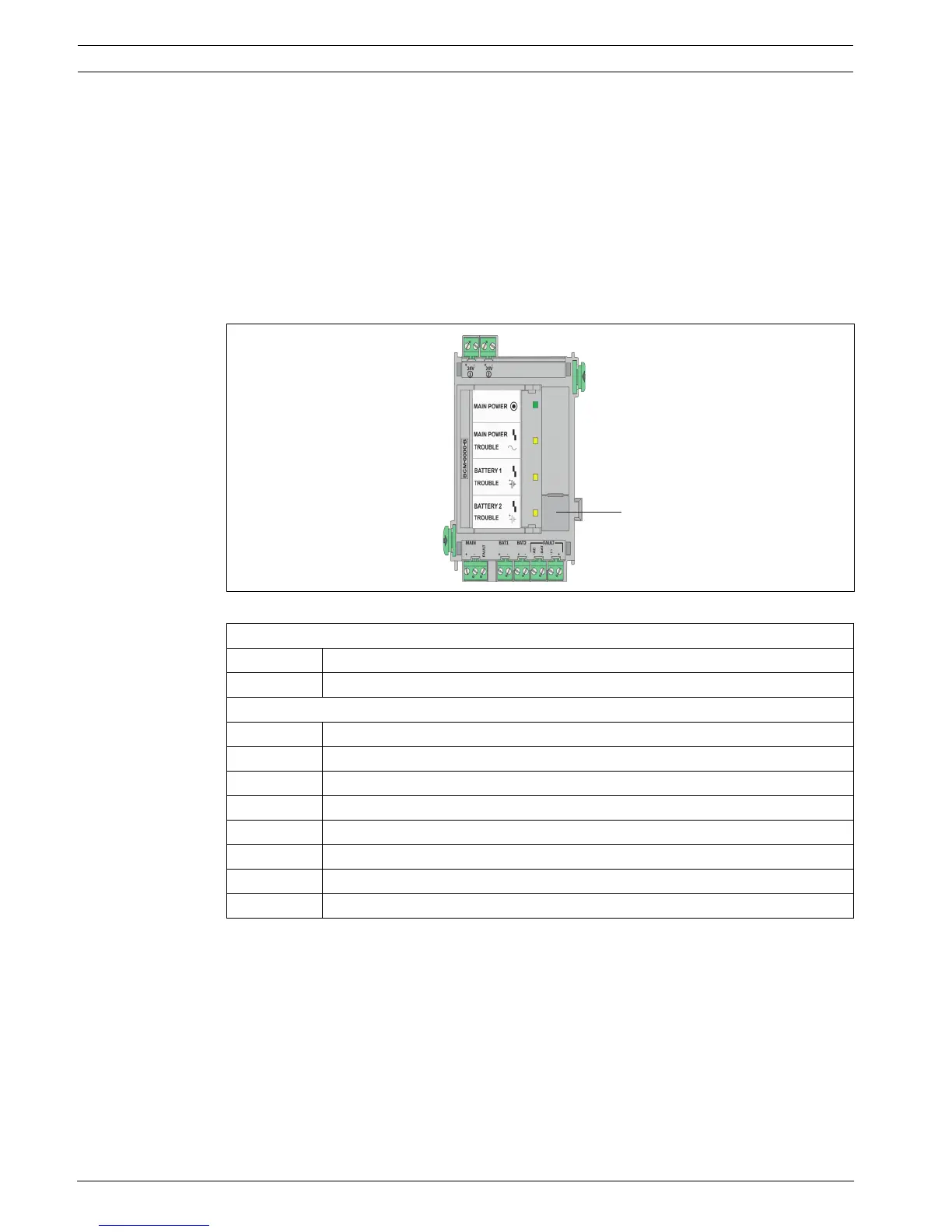
4.9.3 BCM-0000-B Battery Controller Module
The BCM-0000-B Battery Controller Module monitors the power supply of the entire panel and
regulates the temperature and time-controlled charging of up to four batteries.
The following functions are available using the keys on the module (see Figure 4.62 (1)):
– The four LEDs on the module light up as a confirmation and LED test each time the key is
pressed.
– If the batteries have a voltage of between 18 V and 21 V, the battery charging procedure
can be started manually. Please note that a power supply must be available.
– The 24 V switch outputs can be reset.
The switch output is deactivated if a fault occurs.
Figure 4.62 BCM-0000-B Battery Controller Module
Notes
– The module can only be used with the MPC Panel Controller from software version 2.1
onwards.
– If the FPA-5000 Fire Panel is not supplied with mains power, it can only be started
– if a battery pair is connected to BAT1 and
– no second battery pair is connected to BAT2.
If batteries are connected to the BAT2 connection on the module, the system will
report a battery fault and will not start. This battery fault can only be reset if the
FPA-5000 Fire Panel is supplied with mains power and the BAT 2 connection is con-
figured.
Top connections, from left to right
24 V + | - Switch output +24 V max. 2.8 A (battery buffered, optional)
24 V + | - Switch output +24 V max. 2.8 A (battery buffered, optional)
Lower connections, from left to right
MAIN + | - Power supply unit connection
MAIN FAULT Signal input for power supply unit fault
BAT1 + | - Battery pair 1 connection
BAT2 + | - Battery pair 2 connection
FAULT AC - Switch output for mains fault
FAULT BAT - Switch output for battery fault
FAULT Σ - Switch output for collective fault
FAULT +24 V Switch output +

 Loading...


