Modular Fire Panel Installation | en 111
Bosch Sicherheitssysteme GmbH System Description F.01U.028.089 | 8.0 | 2011.07
– If the FPA-5000 Fire Panel is not supplied with mains power for an extended period,
ensure that the batteries are disconnected.
– When using the module in the FPP-5000 External Power Supply, only one battery pair can
be charged (see Section 4.12 FPP-5000 External Power Supply Unit Kit 24 V/6 A,
page 128).
– Refer to the configuration information in Section 3.9 Configuration of BCM Battery
Controller Module, page 42.
The technical data can be found in Section 7.5.2 BCM-0000-B Battery Controller Module,
page 159.
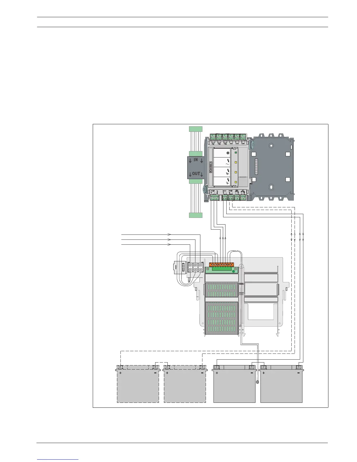
Wiring Diagram
Figure 4.63 Wiring diagram for BCM-0000-B

 Loading...


