112 en | Installation Modular Fire Panel
F.01U.028.089 | 8.0 | 2011.07 System Description Bosch Sicherheitssysteme GmbH
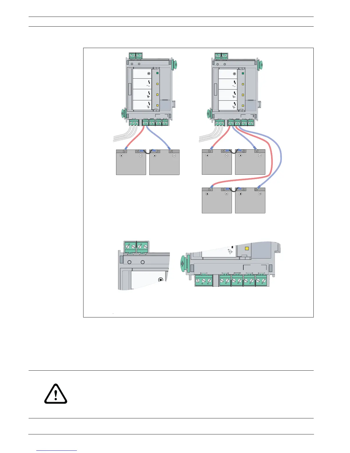
Battery Connection
Figure 4.64 BCM-0000-B battery connection
Cable Set
A cable set is supplied and contains 2 connection cables: BCM/battery (90 cm) and battery/
battery (17 cm).
If you want to install the batteries in a power supply housing, you require the CBB 0000 A
Cable Set (BCM/battery cable length 180 cm.
B
-
00
0
0-MCB
+ - + -
24V 24V
MAIN BAT1 BAT2 FAULT
T
LUA
F
CA
-
TA
B
-
MAIN POWER
MAIN POWER
TROUBLE
TROUBLE
TROUBLE
BATTERY 1
BATTERY 2
+ - + - + - +
- Σ
1 2
B-
00
0
0
-
M
CB
+ - + -
24V 24V
MAIN BAT1 BAT2 FAULT
T
LU
AF
MAIN POWER
MAIN POWER
TROUBLE
TROUBLE
TROUBLE
BATTERY 1
BATTERY 2
1 2
CA -
T
A
B
-
+ - + - + - +
- Σ
V 4
2
V 42
V 4
2
+
WARNING!
There is a risk of injury if no temperature sensor is positioned between the batteries.
The temperature sensor is supplied with the power supply bracket and protects the batteries
against overheating. If the sensor is not positioned correctly, the batteries can overheat and
explode.
Position the temperature sensor between the batteries.

 Loading...


