Modular Fire Panel Installation | en 137
Bosch Sicherheitssysteme GmbH System Description F.01U.028.089 | 8.0 | 2011.07
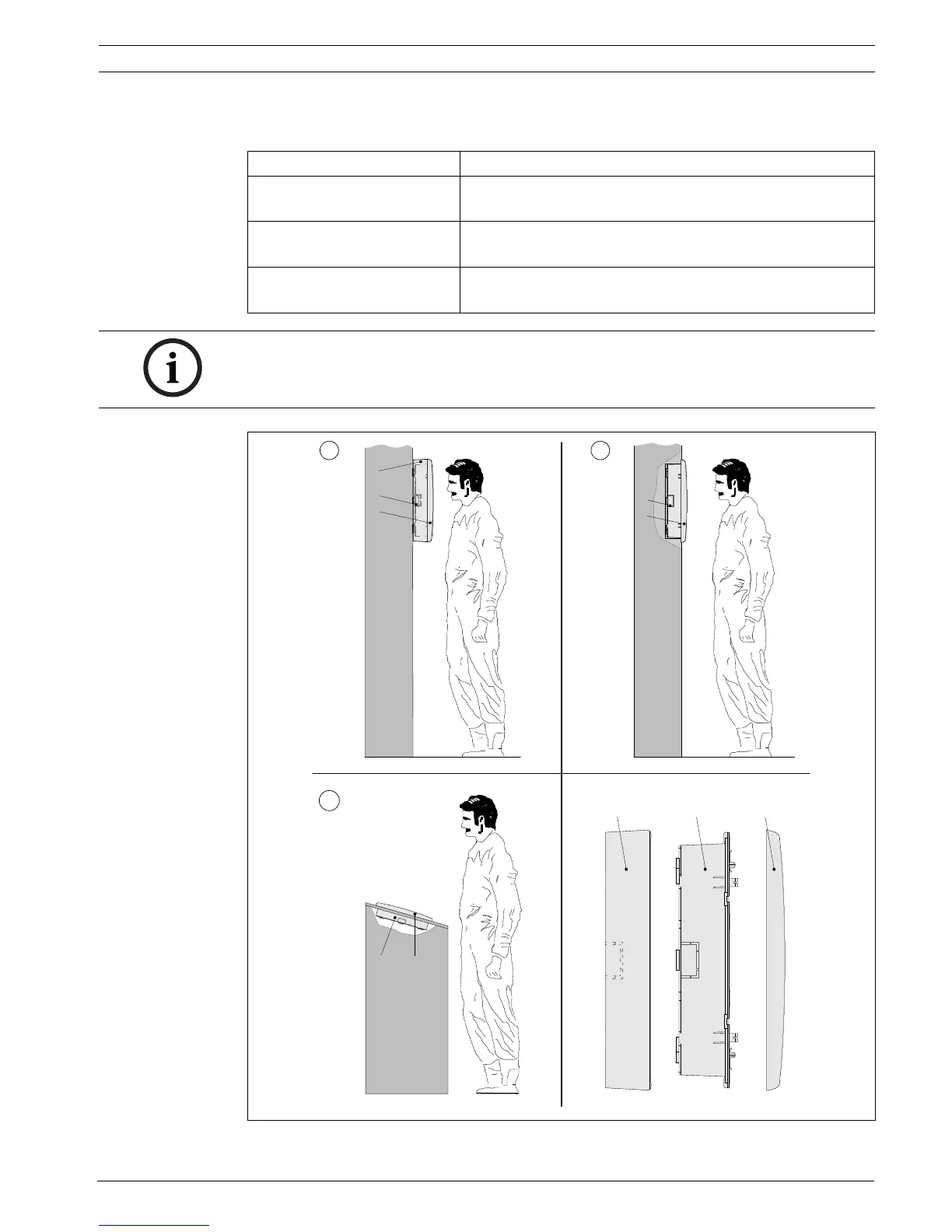
Installation
Follow the instructions for the required installation version.
Figure 4.91 FMR-5000 installation variations
Installation version Installation instructions
Surface wall mounting
(see figure, I)
See Figure 4.92, Page 138 to Figure 4.94, Page 140
(Steps 1 to 13) and Figure 4.95, Page 141
Flush wall mounting (see
figure, II)
See Figure 4.92, Page 138 to Figure 4.94, Page 140
(Steps 1 to 13) and Figure 4.96, Page 142
Tilted installation
(see figure, III)
See Figure 4.92, Page 138 to Figure 4.94, Page 140
(Steps 1 to 13) and Figure 4.97, Page 143
NOTICE!
Dismantle the operating unit before housing installation. This avoids damage to the touch
screen and makes it easier to screw in the lower fixing screws.
I
CBA
II
III
CB
C
B
A
C
B

 Loading...


