EasyManuals Logo

Bosch FPA-5000 System Description

Bosch FPA-5000
178 pages
To Next Page IconTo Next Page
To Previous Page IconTo Previous Page
Page #80 background imageLoading...
Page #80 background image
80 en | Installation Modular Fire Panel
F.01U.028.089 | 8.0 | 2011.07 System Description Bosch Sicherheitssysteme GmbH
Information on power supply brackets can be found in Section 4.5 Power Supply Brackets,
page 72.
The technical data can be found in Section 7.3.6 UPS 2416 A Universal Power Supply 24 V/6 A,
page 156.
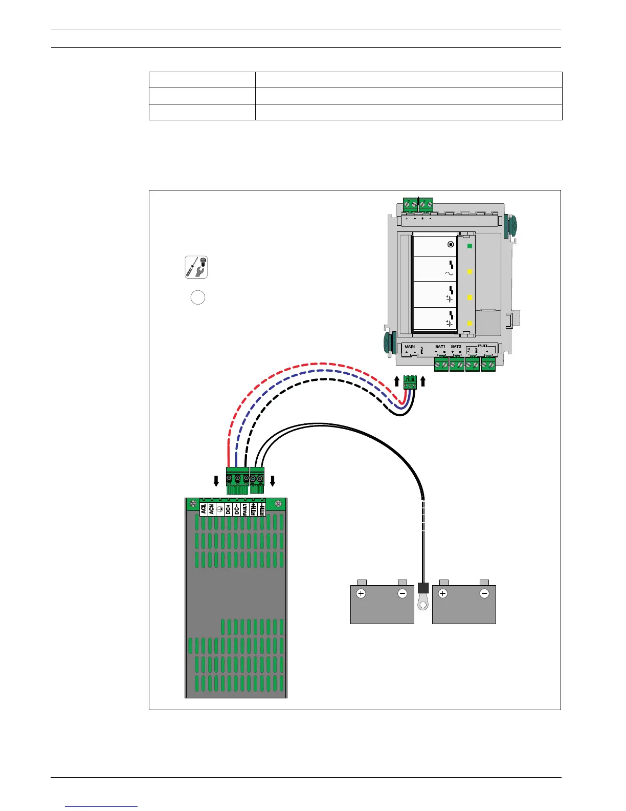
Figure 4.30 Installation of UPS 2416 A in FPO-5000-PSB1 (1)
Power supply bracket Housing
FPO-5000-PSB1 PSS 0002 A, PSB 0004 A
FPO-5000-PS-CH HCP 0006 A, HBC 0010 A, HBE 0012 A
BCM-0000-B
UPS 2416 A
1
UPS 2416 A FPO-5000-PSB1
MAIN POWER
MAIN POWER
TROUBLE
BATTERY 1
BATTERY 2
TROUBLE
TROUBLE
24 V
24 V
Σ
24 V
B
-
0
0
0
0
-
MCB

Table of Contents

Other manuals for Bosch FPA-5000

Questions and Answers:

Question and Answer IconNeed help?

Do you have a question about the Bosch FPA-5000 and is the answer not in the manual?

Bosch FPA-5000 Specifications

General IconGeneral
Max Number of Detectors per Loop254
DisplayLCD
Network CapabilityYes
Power Supply24 V DC
Operating Temperature-5°C to +50°C
Communication PortsEthernet
Humidity Range95% non-condensing

Related product manuals