EasyManuals Logo

Bosch Solution 6000-IP Installation Guide

Bosch Solution 6000-IP
164 pages
To Next Page IconTo Next Page
To Previous Page IconTo Previous Page
Page #28 background imageLoading...
Page #28 background image
Solution 6000-IP
Installation Manual Wiring Diagrams
3-6
Bosch Security Systems 10/22 BLCC615I
+
-
GREEN
YELLOW
YELLOW
16-18V AC
24 VA
ZONE 2
ZONE 4
ZONE 1
ZONE 3
N/C
N/C
N/C
N/C
N/C
ZONE 6
ZONE 8
ZONE 5
ZONE 7
N/C
N/C
N/C
N/C
LAN B
LAN -
LAN A
LAN +
Keypad /
LAN Expansion
Device
Horn
Speaker
Strobe Light
+
-
12V DC
7.2AH Sealed
Lead Acid Battery
Accessories
(e.g. PIR Detectors)
Siren Tamper Switch
Connect To
Cabinet Tamper
To Zone Terminals
+
NC
COM
-
-
+
Smoke
Detector
RF
Receiver
Connect
To
Accessory
Power
GND
+12V
RF DATA
Earth Connection
Spade For Surge Protection
Panasonic
LC-P127R2P
or Equivalent
Ouput 5
Relay Output
24V D.C. 2Amp
Relay COM
Terminal
Programming
Shunt
The maximum
continuous
combined
current draw
from the +12V,
LAN + and
C+ terminals
must not
exceed 1 Amp
Piezo Siren
+
-
3K3
Fit the supplied 3K3
resistor
across the piezo
siren so the panel
can monitor the
connection.
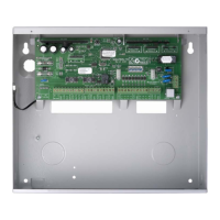
Figure 25: Wiring Diagram

Table of Contents

Other manuals for Bosch Solution 6000-IP

Questions and Answers:

Question and Answer IconNeed help?

Do you have a question about the Bosch Solution 6000-IP and is the answer not in the manual?

Bosch Solution 6000-IP Specifications

General IconGeneral
Event LogYes
Areas1
Partitions1
Outputs2
CommunicationIP, GSM
Mobile AppYes
AutomationYes
System TypeHybrid
Battery BackupYes
KeypadsUp to 8

Related product manuals