S83/85 Ultrasonic Generator System Installation
A40-064 Rev 0 Page 40
5.3 Immersible Transducer Installation, Wiring
5.3.1 Wiring Procedures
The following table contains steps for wiring a junction box.
Note: These steps apply when wiring all three styles of junction boxes to immersible transducers.
Step Action
1 If installing CB-type immersible transducers, prep incoming and outgoing RF
cables. (Refer to Preparing an RF Cable.)
2 Refer to the wiring diagram for your installation.
Route wires from the immersible transducer and the RF cable into the
junction box.
3 Strip all wire ends approximately ½ inch (immersible transducer and RF
cable wires).
4 Match the colored wires (that is, red to red or black to black).
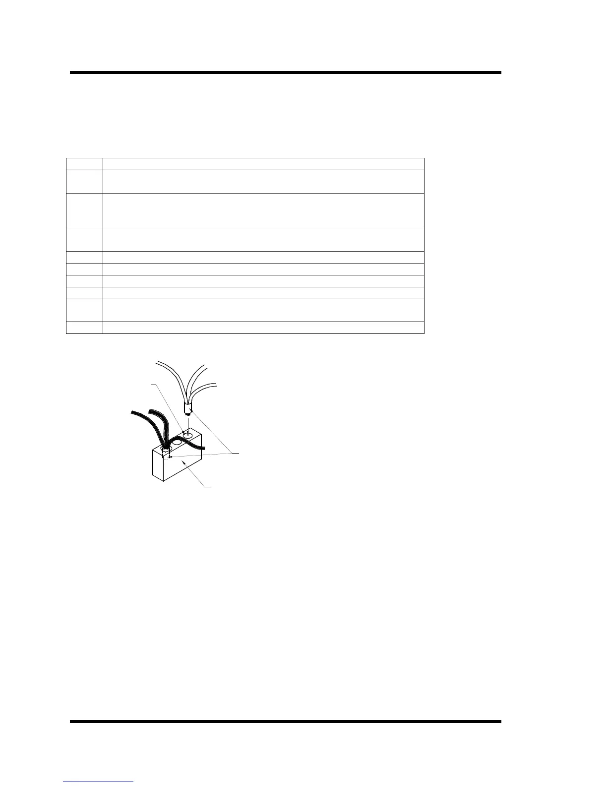
5 Insert the matching colored ends into the barrel crimp (Figure 5-2).
6 Crimp the barrel connector with a proper crimping tool.
7 Fill the drilled hole in the insulator block with silicon sealant (RTV 102®).
8 Insert the crimped connector into the hole and push in until seated at the
bottom of the hole.
9 Cover the crimp with RTV 102®.
Figure 5-2 Junction Box Terminal Connections
Barrel
Connectors
Hole
Insulator Block