S83/85 Ultrasonic Generator Options
A40-064 Rev 0 Page 94
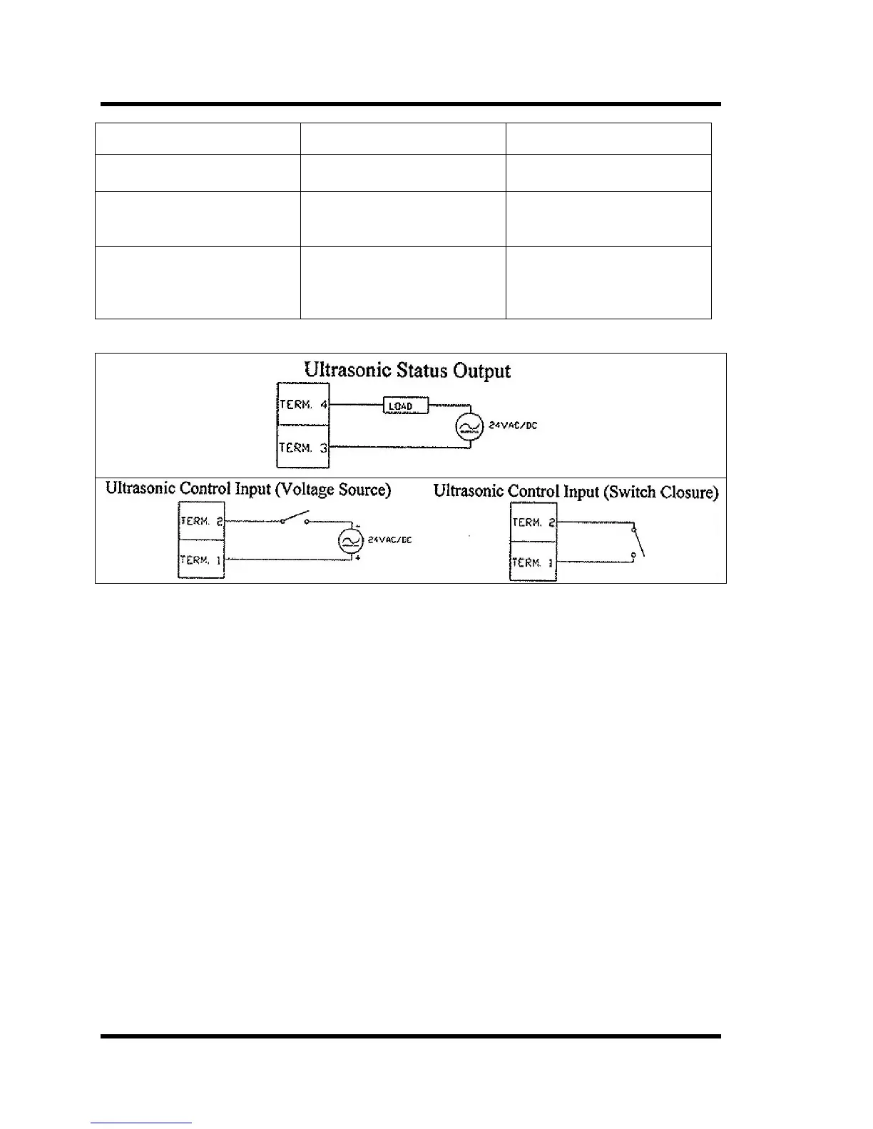
Input Control Type Jumper Settings Terminal Connections
Dry switch closure
(Factory setting)
JP1 on pins 1 and 2
JP2 on pins 1 and 2
U/S on: Close switch
across terminals 1 and 2
24VAC source JP1 on pins 2 and 3
JP2 on pins 2 and 3
U/S on: Connect 24VAC
source across terminals 1
and 2
24VDC source JP1 on pins 2 and 3
JP2 on pins 2 and 3
U/S on: Connect +24VDC
to terminal 1, connect
+24VDC common to
terminal 2
Figure 7-11 External Wiring Diagrams