S83/85 Ultrasonic Generator Options
A40-064 Rev 0 Page 85
Step Action
1 Remove the cover (Figure 7-1)
2 Install the plastic stand-offs onto the back side of the I/O board (Figure 7-2).
3 Place the board into the ultrasonic power supply (Figure 7-3).
4 Install the lug of the green and yellow ground wire to the brass stud on the Power
Oscillator (P/O) board; and plug the other end of the ground wire to jumper E3 on the
I/O board.
5 Line up the I/O 25-pin connector and Remote switch with the slots on the back panel.
Also, make sure the standoffs line up with the holes in the left side panel of the
ultrasonic power supply.
6 Insert the retaining screw through the flat washer, then through the left side panel into
the standoffs in two places. Tighten the screw.
7 Insert the two hex nuts and washers on the D-shell connector screws (Figure 7-3) and
tighten.
8 Make the following connections:
Plug the 2-wire harness into J21 (I/O board) and to J20 (P/O board).
Plug the 25-connector ribbon cable into J8 (I/O board) to J7 (P/O board).
9 Install the cover and retaining screws.
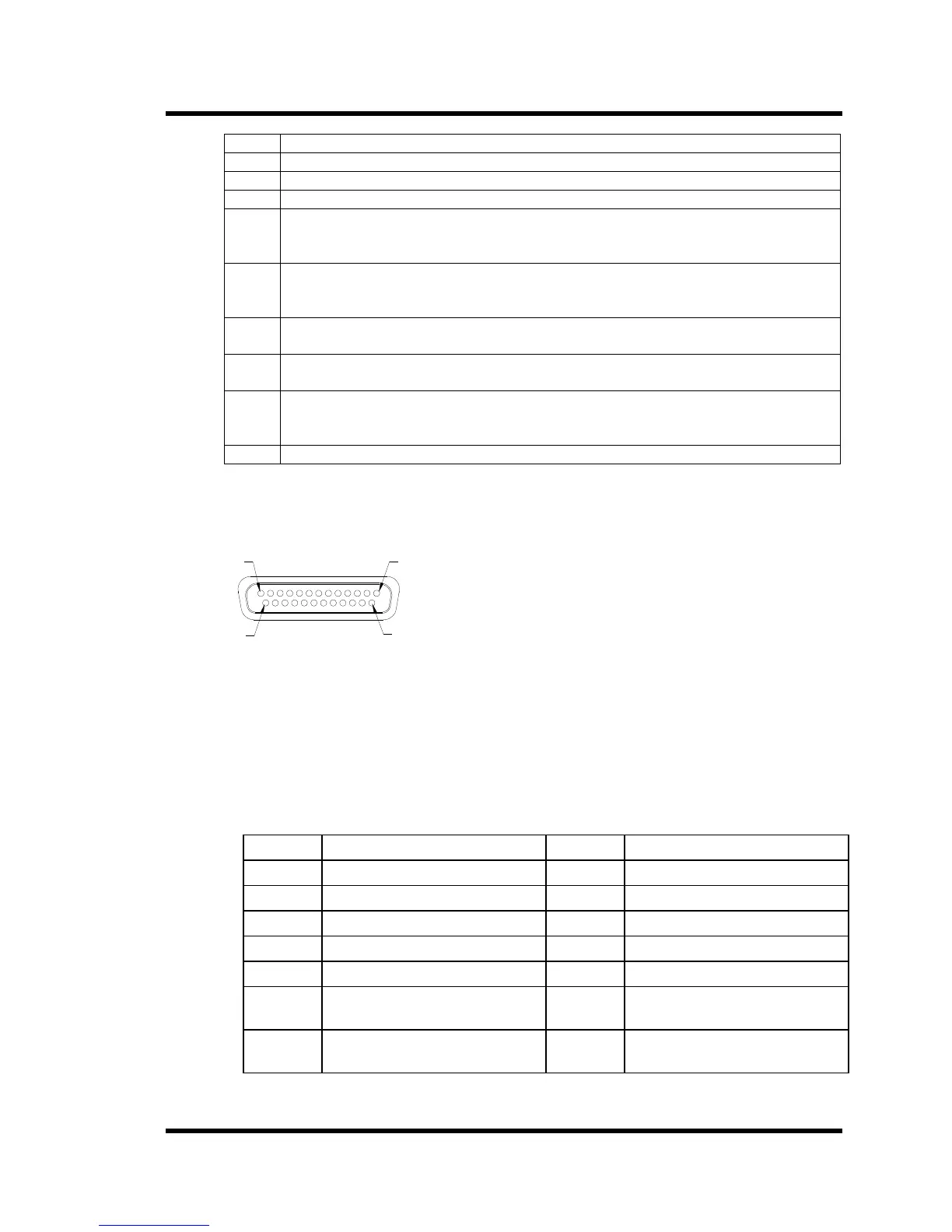
7.1.3 I/O Board Input Signals
Figure 7-4 Connector J2
1
13
25
14
The I/O board is capable for controlling ultrasonic power using either a voltage input (0-10VDC)
or a current input (0-20ma or 4-20ma). This selection is made by the state of pin 25. If pin 25 is
connected to common, current control is selected. If open, voltage control is selected. If current
mode is selected, the state of pin 22 controls which current range is used. If pin 22 is open, the 4-
20ma range is selected. If pin 22 is closed, the 0-20ma range is selected. If voltage mode is
selected, a 0-10VDC signal is applied between pins 8(+) and 7(-). To activate a function, you
connect the corresponding (Figure 7-4) function pin and the common pin.
Table 12 I/O Board Input Functions
Pin No. Function Pin No. Function
1 Reset 13 Common
2 Rate 15 Ultrasonics (U/S) ON/OFF
3 Power Modulation 16 Sweep
4 Interlock 17 Not Used
6 Current Mode Control Input 19 U/S Status
7 Input Common 22 Current Control Select
0-20ma – 4-20ma
8 0-10 VDC power control 25 Current or Voltage Control
Select