S83/85 Ultrasonic Generator Options
A40-064 Rev 0 Page 93
Attach and lock the I/O board’s ribbon cable to the power supply’s main board header J7.
Attach and lock the I/O board’s two wire harnesses to the power supply’s main board
header J20.
Place the top cover back on the power supply and secure to the sides with screws.
7.3.4 OEM I/O Operation
The OEM I/O is functionally in parallel with the front panel US switch. Two external
functions are provided with the I/O board, ultrasonics ON/OFF and ultrasonics ON/OFF
status. Both functions are accessed through a 4 position terminal block located on the
end of the I/O board. Ultrasonics can be toggled on or off from a dry switch closure or a
24VAC or 24VDC source, depending on how the I/O board is configured. The factory
setting is for dry switch closure. Ultrasonic ON/OFF status is read from a normally open
output relay contact on terminals 3 and 4 of the terminal block.. Ultrasonic ON/OFF
control is activated from terminals 1 and 2 of the terminal block.
7.3.5 Specifications
Isolation Type Voltage Range Maximum Current
Input: Optical 12-30 VDC
10-27 VAC
N/A
Output: Relay 0-30 VDC
0-48 VAC
N/A
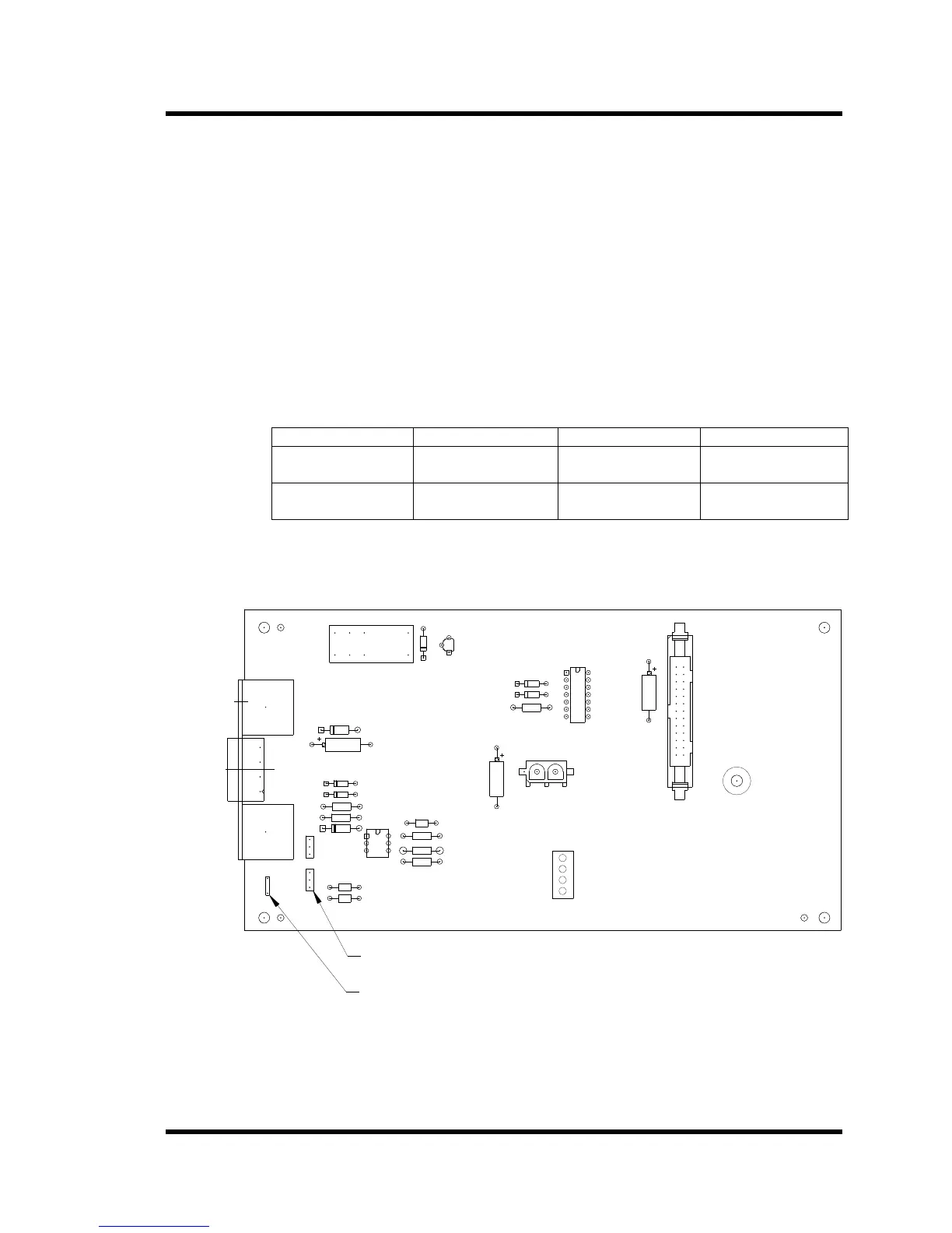
The OEM I/O board can be configured to activate ultrasonics with an external switch
closure or an external 24 VAC oe 24 VDC voltage source.
Figure 7-10 OEM I/O Configuration
1 2 31 2 3
JP2 ON PINS 2 AND 3
SET: JP1 ON PINS 2 AND 3
2) FOR 24VAC OR 24VDC ACTIVATION
JP2 ON PINS 1 AND 2
SET: JP1 ON PINS 1 AND 2
TERMINAL 4
TERMINAL 3
TERMINAL 2
TERMINAL 1
CONNECTIONS J2
TERMINAL BLOCK
TERMINALS 4 AND 3: RELAY OUTPUT
TERMINALS 2 AND 1: U/S ACTIVATION
1) FOR DRY SWITCH ACTIVATION
U/S ACTIVATION PROGRAMMING MODES
100-242-324R REV 3
BRANSON ULTRASONICS CORP.
OEM I/O PC BD
JUMPERS
GROUND WIRE CONNECTION
JP1 JP2