S83/85 Ultrasonic Generator Options
A40-064 Rev 0 Page 86
7.1.4 I/O Board Output Functions
The I/O board outputs two status signals through isolated relay contacts.
• A “FAULT OUTPUT” contact closure occurs between pins 10 and 18 when a
generator fault condition exists.
• An “U/S output” contact closure occurs between pins 19 and 18 when U/S is
on.
If the current control mode is selected, a current proportional to power is output on pin
24.
If the voltage control mode is selected, a voltage proportional to power is output between
pins 5 and common (7) or (13).
A +10.0VDC reference voltage is output on pin 9 (1ma max load).
A +15VDC supply (10ma max load) is output on pin 14.
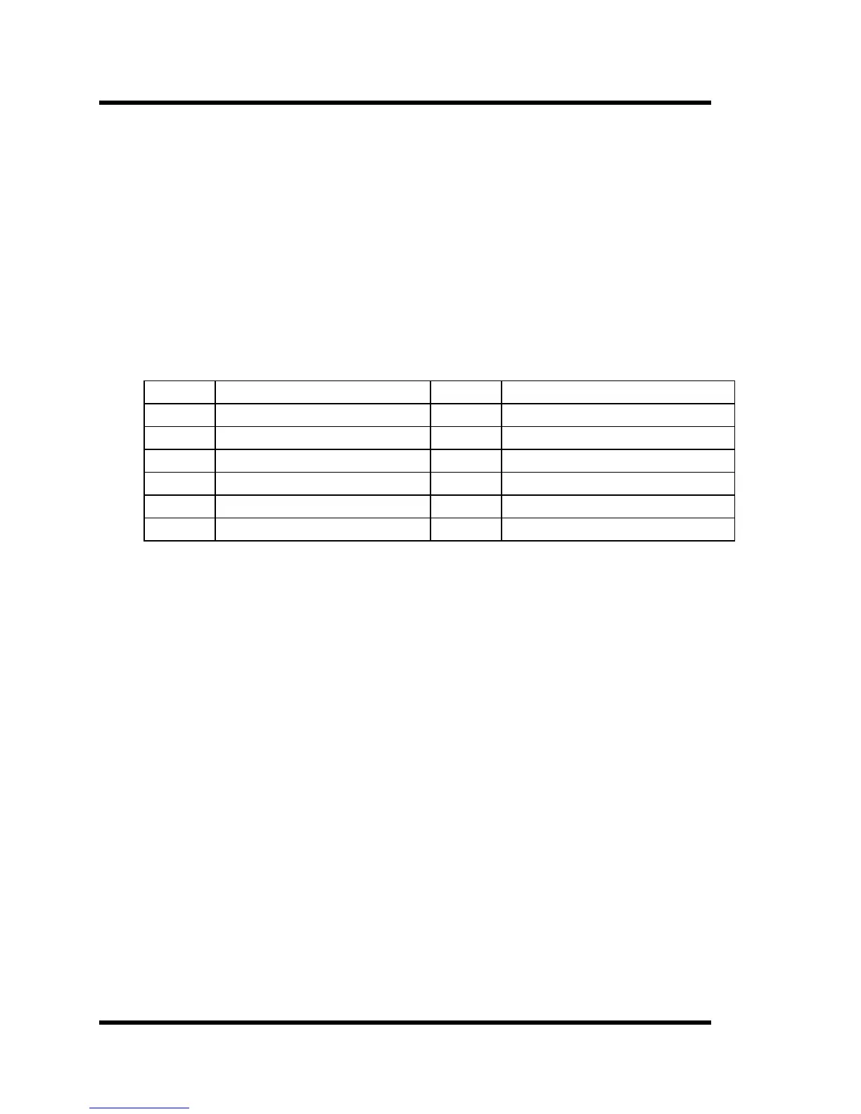
Pin No. Function Pin No. Function
5 0-10 VDC power meter 14 +15VDC Supply (10ma max.)
7 Common 18 Relay Output Common
9 +10VDC Reference (1ma max.) 20 Do Not Use
10 Fault Relay N.O. Contact 21 Do Not Use
11 Not Used 23 Not Used
12 Do Not Use 24 Power Level Current Output
Full Feature I/O Board Circuits
I/O Board Analog Functions
The I/O Board also carries four analog signals:
1. Power Adjustment (input) - an external 0-10 VDC source controls the power level of the
ultrasonic power supply.
2. Power Level (voltage) - outputs the power level of the ultrasonic power supply via a 0-10
VDC signal. Figures A-5, A-6, A-7, and A-8 contain circuit diagrams for circuits that handle
the input and output functions of the I/O board.
3. Current Adjustment (input) - an external 4 to 20ma or selectable (0-20ma) current source,
controls the power level of the ultrasonic power supply.
4. Power Level (current output) - outputs the power level of the ultrasonic power supply by a
current output, (either 0-20ma or 4-20ma selectable).
Note: The I/O board contains a set pot labeled R86 that can be used to control ultrasonic power
when using external control (i.e., PLC). To enable this feature, jumper JP2 pins 1+2. While
the jumper is in place you can no longer control power using J2 Pin 8.