S83/85 Ultrasonic Generator Options
A40-064 Rev 0 Page 84
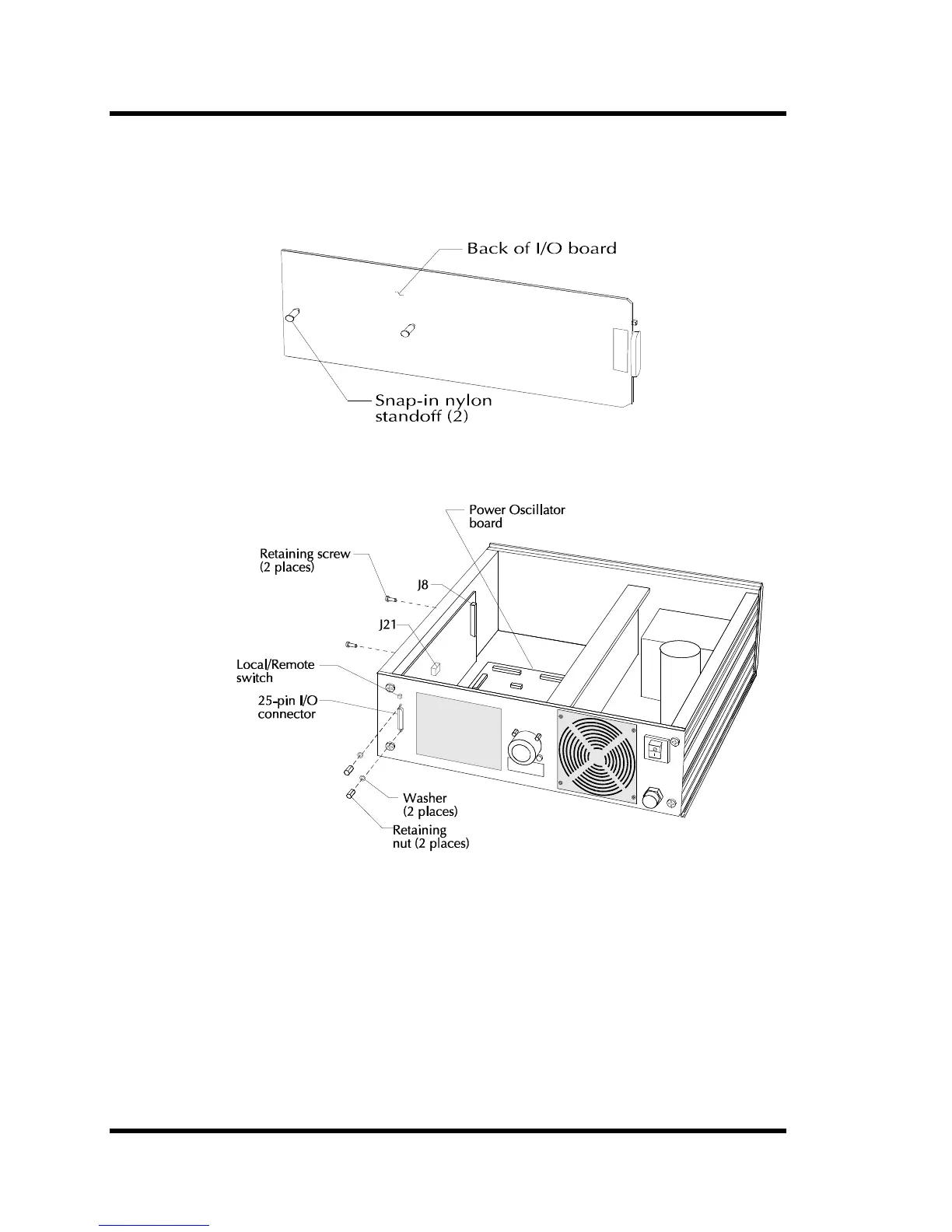
7.1.2 Installing the I/O Board
Figures Figure 7-2 and Figure 7-3 contain illustrations showing how to install the I/O board in the
power supply. Study the illustrations, then follow the instructions in the table below.
Figure 7-2 Installing Standoffs
Figure 7-3 Installing I/O Board
Note: If you are replacing an I/O board from an 8000 Series Generator to an 8500 Series
connection on oscillator board is either Pin J4 or J12.