S83/85 Ultrasonic Generator Troubleshooting
A40-064 Rev 0 Page 79
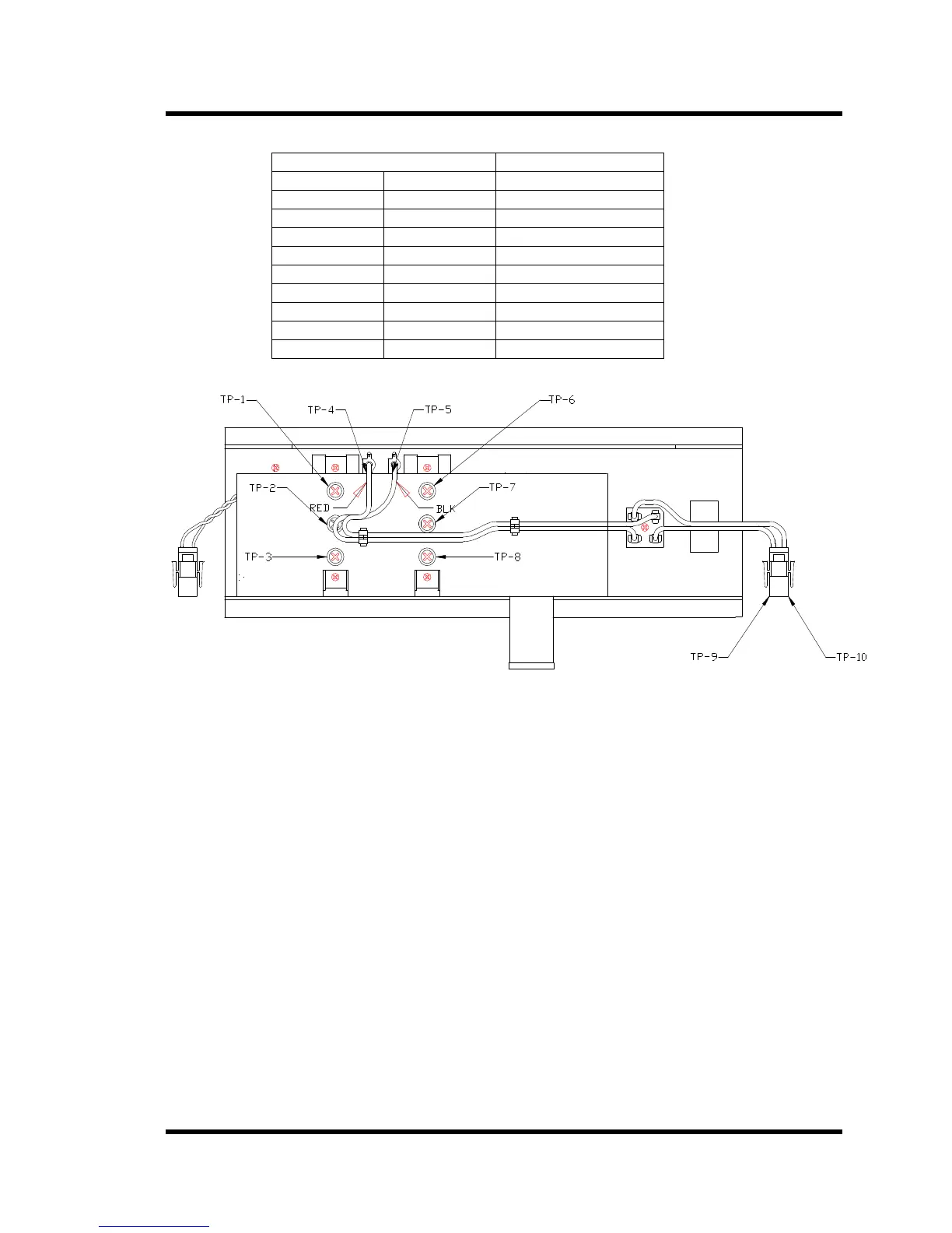
Table 10 Diode Resistances
Diode meter test leads Reading
+ -
TP-1 TP-2 OPEN-CIRCUIT
TP-2 TP-3 0.35-0.55
TP-3 TP-1 0.35-0.55
TP-6 TP-7 OPEN-CIRCUIT
TP-7 TP-8 0.35-0.55
TP-8 TP-6 0.35-0.55
TP-5 TP-4 0.7-1.0
TP-9 TP-10 OPEN-CIRCUIT
TP-10 TP-9 OPEN-CIRCUIT
Figure 6-1 Driver Board Test Points
6.5 Cavitation Erosion
Cavitation erosion is a natural consequence of operating ultrasonics. It appears initially as a
dulling of the radiating surface and proceeds to pitting and eventually may penetrate the metal so
that the tank or transducer becomes unusable. The rate of erosion depends upon the ultrasonic
frequency, the temperature of the liquid, the chemistry in the tank, the hardness of the tank, the
power setting of the generator and many other factors.
6.5.1 Repairing Cavitation Erosion Marks
There is no reliable method of repairing cavitation erosion
6.5.2 Minimizing Cavitation Erosion
To reduce cavitation erosion:
• Operate the ultrasonics only when actually cleaning parts.
• Set the power level to the minimum setting that will produce clean parts.