Operation
6
CLS Pro 600 – Line and Contrast Sensor 55/108
7. If line L2 has to be used for the guiding then the arrow keys
must be used to define the search area. In this case you must
select the search area position and then the search area size
functions ⑤ and then define the search area. Press the ENTER
button. The LEDs inside the ENTER and SETUP keys will be ex-
tinguished. The display will change over from setup mode to
scanning mode.
8. Press the ENTER button. The system will now switch back to
AUTO mode (operating mode).
ð The line setup is finished.
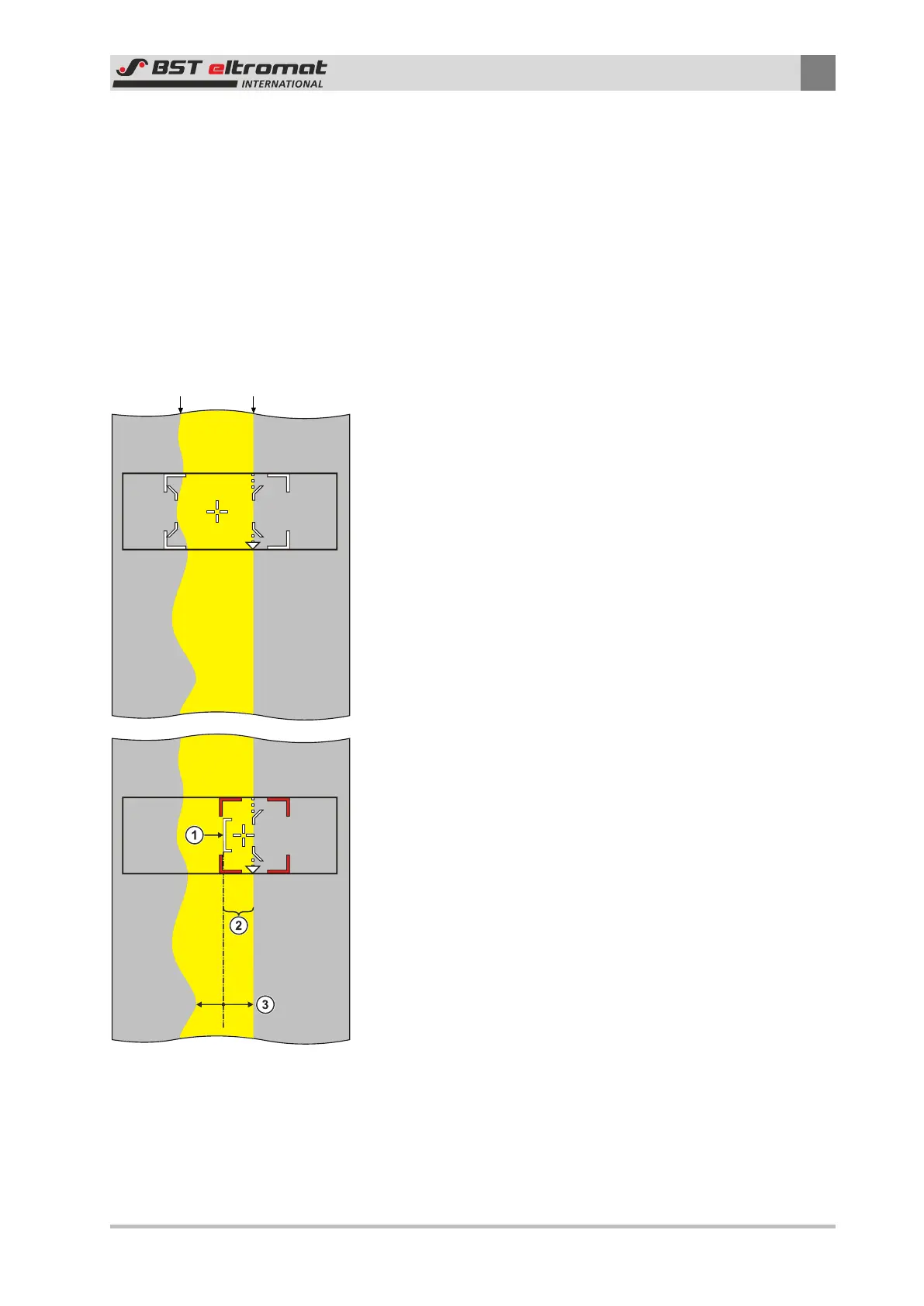
Area Tracking:
If the conditions are present, as shown in the example, then the
displayed pre-selection will be used for the standard settings.
This can result in the controller producing unclean web guiding,
due to the unevenness of LK1.
The Area-Tracking will have to be used in this case. Only one edge
(LK2) will be tracked, but this will be compared by checking the
color of an area alongside the edge. This will enable the noise
spikes to be suppressed and prevent the system from jumping
around.
LK1 can no longer be included, as the search area has been re-
duced. The search area is displayed here. We recommend that the
setting is made so that the left edge ① of the search area ② lies
approx. over half of the smallest point ③ in the line. The area
that has to be checked must always lie on the side of the edge on
which the crosshairs lie.