55
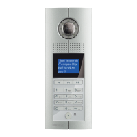
D45 VIDEO DOOR ENTRY SYSTEM
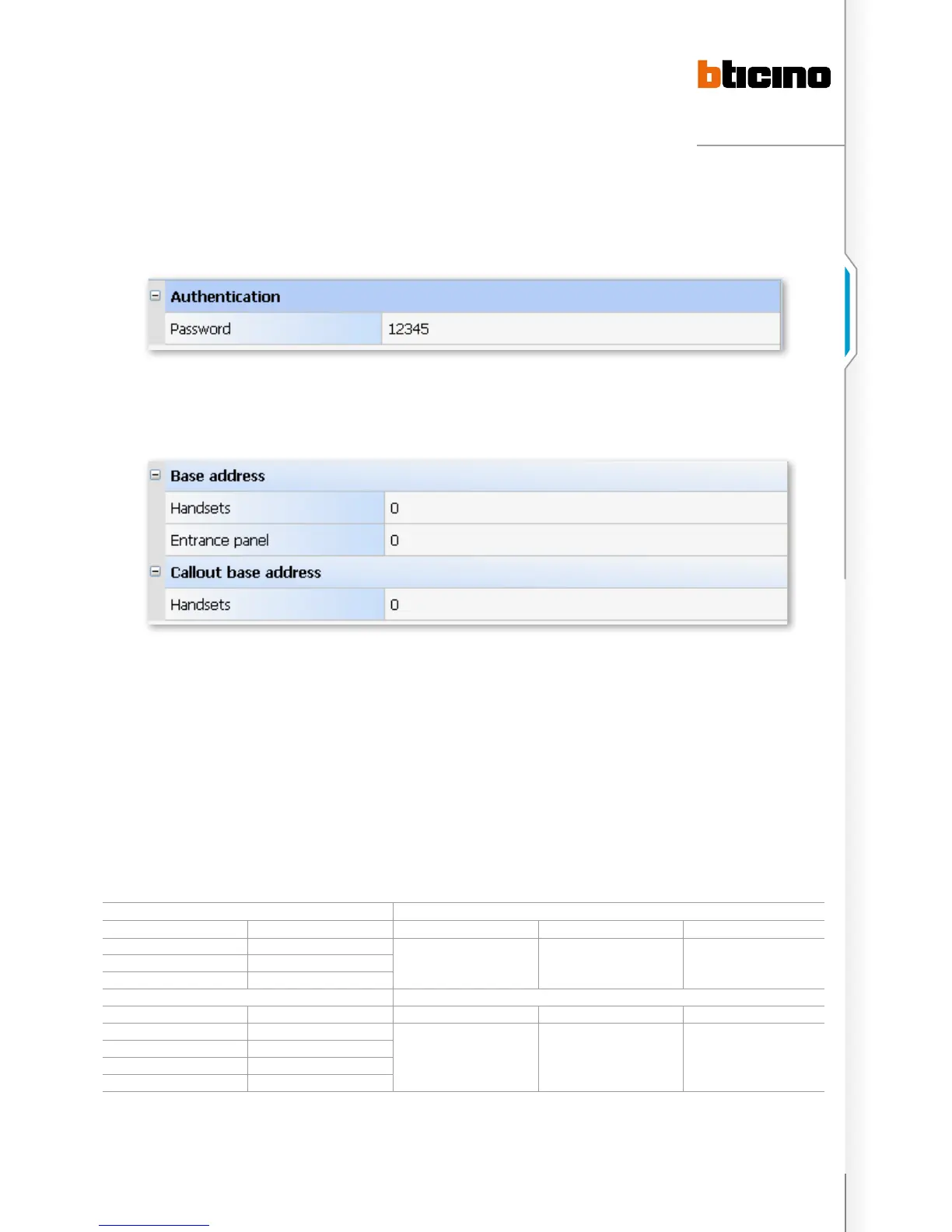
Select the “AUTHENTICATION” node on the left of the main interface and the Password option on the right will be used to
input in the password for the 323011 to download the configuration. The default password is 12345. It’s suggested to still use
this password for later maintenance.
Select the “INTERFACE” node on the left of the main interface. The Handsets under the option of Base address will be used to
configure the base address of handset 323011, which can just use the default value 0. Entrance panel is used to configure the
base address of the EP’s D45/IP interface, which can also use the default value of 0. Handsets under the Callout base address
option will be used to configure the base address of the handset callout at 323011, which can just use the default value of 0.
Select the “HANDSETS” node on the left of the main interface, and then look at the interface on the right,The handset presence
option will be used to select whether the 323011 connects the handset or not (namely whether D45/IP interface is the resident
Riser). If yes, please select Yes; if it’s only used to connect the backbone, select NO. On selecting No, the Lower address, Higher
address, and system address range will become grey, which means that they cannot be set. The Lower address option is used
to input in the lowest address (range 0 to 3999. It must be smaller than the higher address) that connects item 323011 to the
handset. The Higher address option is used to input in the highest address (range 0 to 3999. It must be higher than the lower
address) that connects item 323011 to the handset. The system address range displays the address range of the handset set
for the above two options.
example:
If the first D45/IP interface 1 connects 3 Risers (Riser 1, Riser 2 and Riser 3), the second D45/IP interface 2 will connect 4 Risers
(Riser 4, Riser 5, Riser 6 and Riser 7). Each Riser should be configured as per Mode 1
SET THE HANDSETS OPTION OF D45/IP INTERFACE 1
Riser Serial number Each Riser address range Lower address Higher address 323011address range
Riser 1 0 - 79
0 239 0-239Riser 2 80 - 159
Riser 3 160 - 239
Set the handsets option of D45/IP interface 2
Riser serial number Each Riser address range Lower address Higher address 323011address range
Riser 4 240-319
240 559 240-559
Riser 5 320-399
Riser 6 400-479
Riser 7 480-559

 Loading...