3-30 2007 Buell Lightning: Engine
HOME
Installing Engine in Frame
NOTE
Vehicle should be placed onto the lift with rear tire in the
wheel vise in order to successfully perform this procedure.
1. See Figure 3-37. Install bottle jack and wooden block
under swingarm/oil tank to the rear of the oil line fittings.
NOTE
See Figure 3-40. At this point it is necessary to support main
frame with overhead hoist in order to install rear isolator bolt.
2. Remove ratcheting tie down and block of wood between
rear isolator mount on main frame and swingarm/oil res-
ervoir.
3. See Figure 3-38. With engine on a flat scissors jack,
raise engine and chassis until swingarm and rear isolator
mount align and pivot shaft can be installed.
4. Apply anti-seize to swingarm pivot shaft threads and
tighten swingarm pivot shaf to 24-26 ft-lbs
(32.5-35.2 Nm).
5. Apply LOCTITE 271 (red) and tighten swingarm pivot
shaft pinch bolt to 17-19 ft-lbs (23-25.8 Nm).
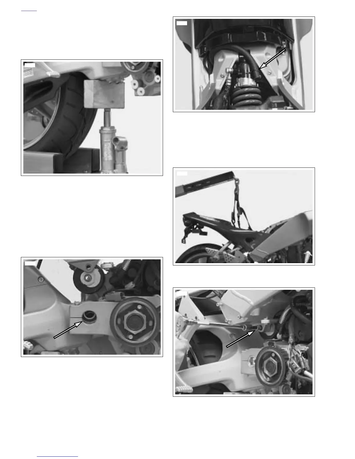
6. See Figure 3-39. Route transmission vent line up
through left side of frame exiting under the left rear side
of the intake cover assembly. Install cable strap to secure
transmission vent line in place. Inspect vent line to verify
space between vent line and rear exhaust.
7. See Figure 3-41. Using the overhead hoist to align the
frame to the rear isolator, install rear isolator bolt and
leave loose at this time.
Figure 3-37. Supporting the Swingarm (Typical)
Figure 3-38. Aligning Swingarm to Crankcase for Pivot
Shaft Installation (Typical)
8719
8771
Figure 3-39. Transmission Vent Line
Figure 3-40. Supporting Vehicle for Assembly (Typical)
Figure 3-41. Installing Rear Isolator Bolt (Typical)
8918
8716
8722