2-50 2007 Buell Lightning: Chassis
HOME
ASSEMBLY
Damper Rod Assembly
Note
Skip to fork assembly if damper rod assembly was not disas-
sembled.
1. See Figure 2-69. Fully thread the damper rod locknut
(10) on to damper rod (11) clockwise till it lightly bottoms.
NOTE
Set both forks to the exact same suspension settings.
2. Adjust rebound assembly for proper range of motion.
a. Lightly turn the rebound adjuster screw on top of the
rebound adjuster assembly (9) counter clockwise till
it stops.
b. Turn the rebound adjuster screw three full turns
clockwise.
3. Fully thread rebound adjuster assembly (9) onto the
damper rod assembly (11) until it lightly bottoms. Do not
tighten.
4. Thread the damper locknut (10) until bottoms lightly on
the rebound adjuster assembly. Do not tighten
5. Turning the rebound adjuster screw (9) counter clock-
wise three full turns or until stops.
6. See Figure 2-71. Tighten the damper locknut (10) to 22-
30 ft-lbs (30-40 Nm).
7. Repeat for other fork assembly.
Fork Assembly
1. See Figure 2-69. Wrap the end of the slider fork (27) and
the slide bushing channel with tape to avoid damaging
the oil seal lip when installing.
2. Install a new dust seal (26) and stopper ring (25) onto
the slider fork (27).
3. Coat the sealing lips of the new oil seal (24) with fork oil
or sealing grease and install onto the slider fork with its
marked side facing the dust seal (26).
4. Remove the tape from the slider fork end.
5. Install the seal spacer (23), the guide bushing (22) and
the slide bushing (21) onto the slider fork (27).
6. Coat the slide bushing (21) and the guide bushing (22)
with fork oil.
NOTE
The outer tube can move freely up and down on the slider
fork. Always hold both the slider fork and outer tube to pre-
vent damage to bushings and seals.
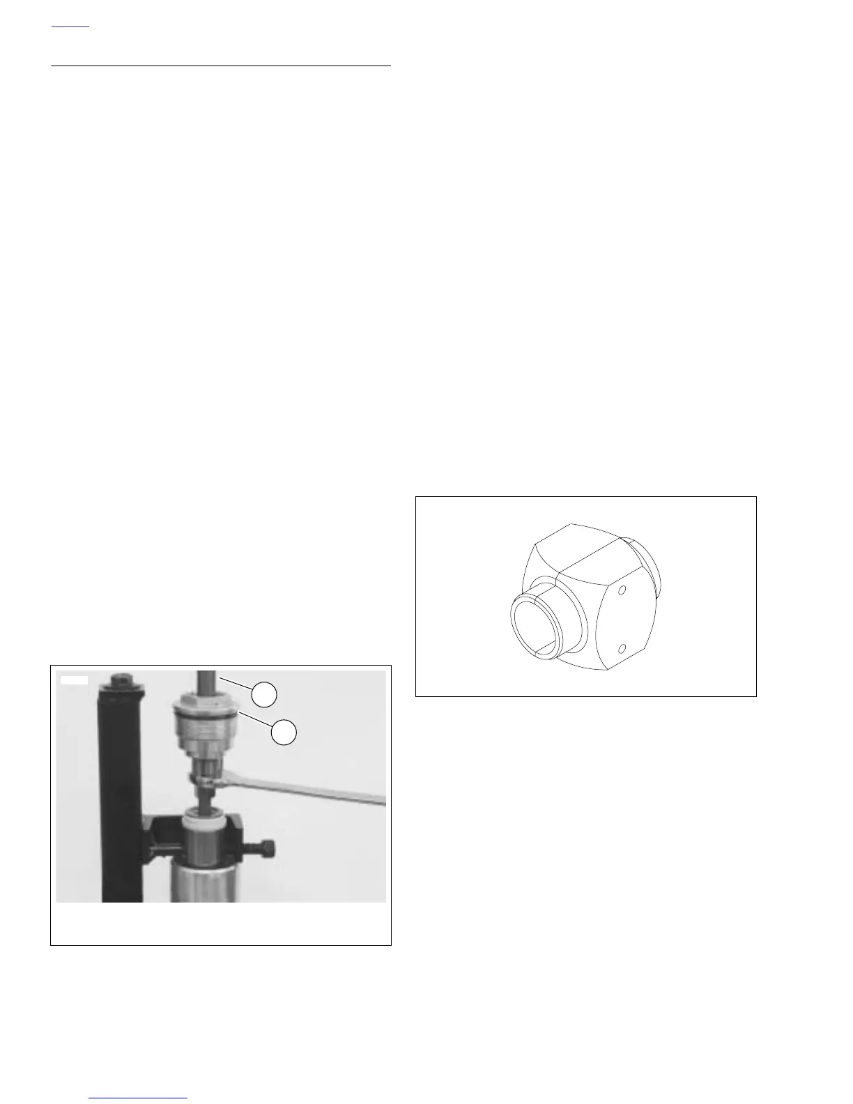
7. See Figure 2-69. Drive the guide bushing (22) with the
seal spacer (23) and oil seal (24) into position in the
outer tube using a FORK SEAL DRIVER (Part No. B-
43721/41mm) and (Part No. B-42571/43mm). See Fig-
ure 2-72.
8. Install the oil seal stopper ring (25) and a new dust seal
(26).
9. Place the fork in the FORK TUBE HOLDER TOOL (Part
No. HD-41177) and clamp into vise horizontally.
10. See Figure 2-69. Install the centering plate (12) onto the
damper assembly (11) and insert the damper assembly
into the slider fork (27).
11. Replace the sealing washer (13) and center bolt (14)
(metric). Tighten the center bolt to 22-30 ft-lbs (30-
40 Nm).
Figure 2-71. Rebound Assembly and Fork Cap Assembly
8479
1. Fork cap assembly
2. Rebound assembly
1
2
Figure 2-72. Fork Seal Driver (B-43721) 41mm
Fork Seal Driver (B-42571) 43mm
b43721