2007 Buell Lightning: Fuel System 4-43
HOME
TROUBLE CODE 11 4.16
GENERAL
Throttle Position Sensor
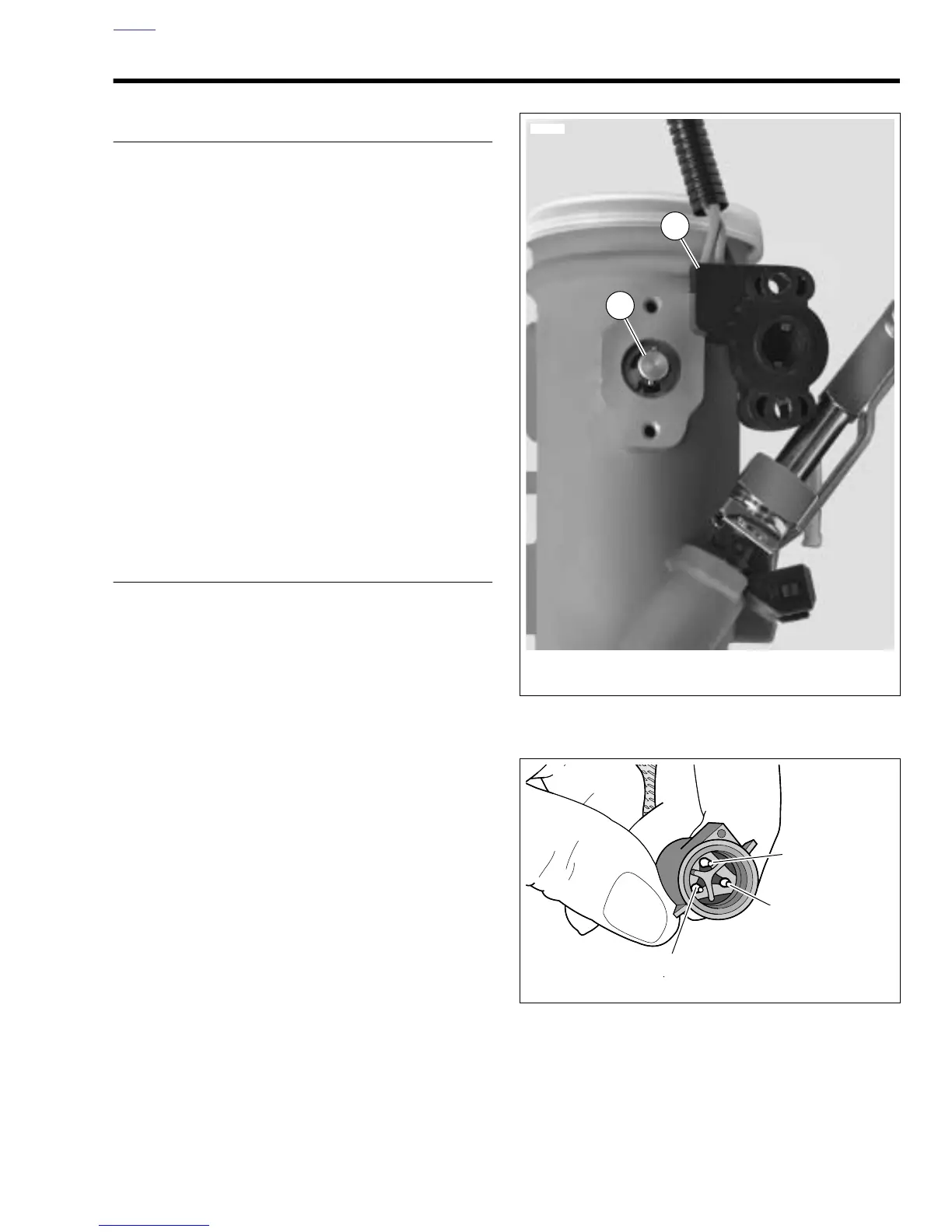
See Figure 4-32. The throttle position sensor (TP sensor) is
supplied 5.0 volts from the ECM (5v REF) and sends a signal
back to the ECM (TP sensor signal) which varies according to
throttle position. The output signal from the TP sensor varies
from:
●
0.5-1.5 volts at idle (closed throttle).
●
3.9-4.9 volts at wide open throttle.
A Code 11 will set if the TP sensor signal voltage does not fall
within the acceptable range.
NOTE
If the TP sensor is removed and/or replaced, the sensor must
be calibrated using Digital Technician (Part No. HD-44750).
For replacement of TP sensor see 4.37 THROTTLE POSI-
TION SENSOR.
DIAGNOSTICS
Diagnostic Tips
TP sensor voltage should increase at a steady rate as throttle
is moved from idle to wide open throttle. An open or short to
ground in R/W or BK/W wires will also result in a Code 11.
Check for the following conditions:
●
Poor connection.
Inspect ECM harness connector for
backed out terminals, improper mating, broken locks
improperly formed or damaged terminals, poor terminal-
to-wire connection and damaged harness.
●
Perform 4.7 WIGGLE TEST
to locate intermittents.
If
connections and harness check out OK, monitor TP sen-
sor voltage using DVOM while moving related connec-
tors and wiring harness. If the failure is induced, the
DVOM display will change.
●
TP sensor scaling.
Observe the TP sensor voltage dis-
play while opening the throttle with engine stopped and
ignition switch ON. Display should vary from closed throt-
tle TP sensor voltage (when throttle is closed) to greater
than 4.0 volts (when throttle is held wide open). As the
throttle is
slowly
moved, the voltage should change
gradually without spikes or low voltages being observed.
Diagnostic Notes
The reference numbers below correlate with the circled num-
bers on the Code 11 flow charts.
1. Connect BREAKOUT BOX (Part No. HD-42682) to ECM.
See 4.6 BREAKOUT BOX.
Figure 4-32. TP Sensor Assembly
Figure 4-33. TP Sensor Terminals [88A]
1. Throttle position sensor and harness
2. Throttle shaft
12502
2
1
b0651x4x
A (R/W Wire)
B (V/Y Wire)
C (BK/W Wire)