3-86 2007 Buell Lightning: Engine
HOME
OIL FILTER MOUNT 3.16
GENERAL
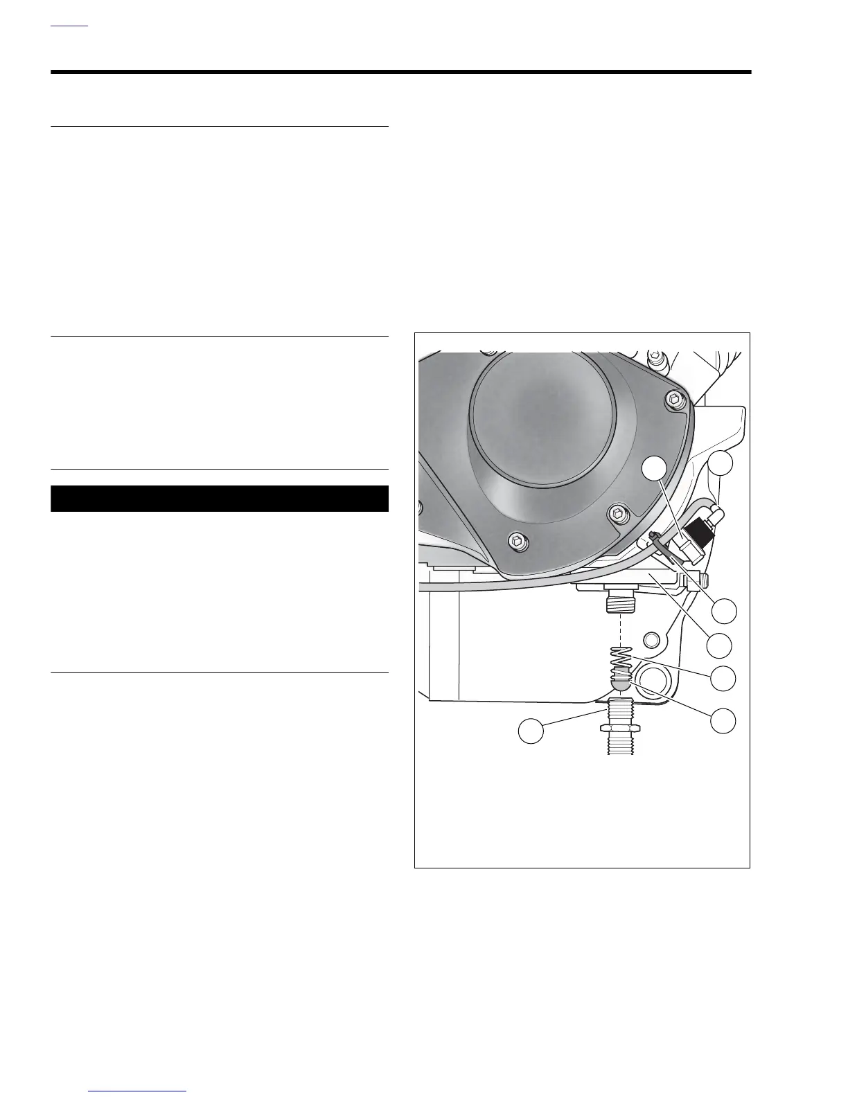
See Figure 3-122. Oil is pressure-fed from the oil pump to the
oil cooler via an external steel line. From the oil cooler, oil
flows to the oil filter mount. Oil travels through the filter mount
into the filter through the outer filter holes.
Adequate oil pressure activates the oil pressure indicator
switch in the filter mount, which turns off the oil pressure indi-
cator lamp.
The check ball in the filter adapter opens at 4-6 psi (28-41
kPa) oil pressure. Filtered oil leaves the filter, flowing past the
check ball.
DISASSEMBLY
1. Remove chin fairing. See 2.37 CHIN FAIRING.
2. Remove oil filter. See 1.5 ENGINE LUBRICATION SYS-
TEM.
3. See Figure 3-122. Remove filter adapter (6) from filter
mount (3). Remove check ball (5) and spring (4).
CLEANING AND INSPECTION
11WARNING1WARNING
Compressed air can pierce the skin and flying debris
from compressed air could cause serious eye injury.
Wear safety glasses when working with compressed air.
Never use your hand to check for air leaks or to deter-
mine air flow rates. (00061a)
Thoroughly clean all parts in cleaning solvent. Blow out holes
and passages using compressed air.
ASSEMBLY
NOTE
The filter adapter has identical ends; either end may be
installed into the filter mount.
1. Apply several drops of LOCTITE 243 (blue) to last few
threads on that end of the filter adapter which is installed
into filter mount. Do not apply LOCTITE to adapter
threads on filter element side.
2. Install filter mount components.
a. Place spring (4) and check ball (5) into threaded
hole at center of mount.
b. Push threaded end of filter adapter (6) against
check ball to compress spring.
c. Screw adapter into threaded hole. Tighten to 96-144
in-lbs (11-16 Nm).
3. Install a new filter and fill oil reservoir with proper oil. See
1.5 ENGINE LUBRICATION SYSTEM.
4. Install chin fairing. See 2.37 CHIN FAIRING.
5. Install cable strap securing oil pressure switch wire to oil
pressure switch.
Figure 3-122. Oil Filter Mount Assembly
1. Oil pressure indicator switch
2. Indicator lamp wire
3. Cable strap to secure indicator lamp wire
4. Oil filter mount (part of right crankcase half)
5. Spring
6. Check ball
7. Filter adapter
b1032c3x
2
1
7
5
4
6
3