2007 Buell Lightning: Engine 3-85
HOME
CLEANING AND INSPECTION
11WARNING1WARNING
Compressed air can pierce the skin and flying debris
from compressed air could cause serious eye injury.
Wear safety glasses when working with compressed air.
Never use your hand to check for air leaks or to deter-
mine air flow rates. (00061a)
1. Clean all parts in cleaning solvent. Blow out holes and oil
passages with compressed air.
2. See Figure 3-120. Inspect both gerotor sets for wear.
a. Mesh pieces of each set together as shown.
b. Use a feeler gauge to determine clearance.
c. The SERVICE WEAR LIMIT between gerotors is
0.004 in. (0.102 mm). Replace gerotors as a set if
clearance exceeds this dimension.
d. Measure thickness of feed gerotors with a microme-
ter. Replace gerotors as a set if they are not the
same thickness.
3. See Figure 3-118. Check gear shaft teeth for damage or
wear. Replace if necessary.
ASSEMBLY/INSTALLATION
NOTES
● If any oil line fittings are found to be loose, or not oriented
in the proper position, those fittings must be removed
and thoroughly cleaned. After cleaning, apply LOCTITE
565 Sealant to the fitting and re-install to the correct ori-
entation. When tightening oil lines, always support the oil
line fitting with a wrench to maintain proper orientation
and prevent damage to the oil line fitting.
● Liberally coat all moving parts with clean engine oil to
ensure easy assembly and smooth operation at start-up.
1. See Figure 3-118. Install gear shaft through body. Posi-
tion thrust washer over end of shaft. Install new retaining
ring into groove in shaft.
2. Insert inner gerotor of the gerotor scavenge set over gear
shaft.
3. Place outer gerotor over inner gerotor to complete scav-
enge set.
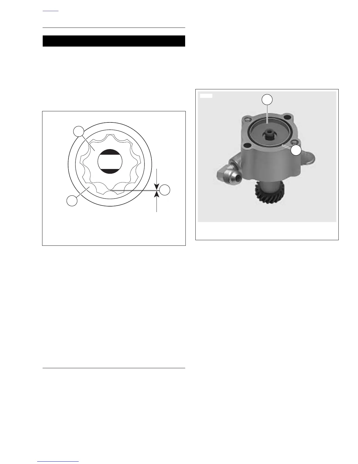
4. See Figure 3-121. Install gerotor separator plate.
5. Install a new o-ring into groove in pump body.
6. See Figure 3-118. Place gerotor feed set over gear shaft.
7. Place cover onto pump body. Install cover TORX screws.
Tighten to 70-80 in-lbs (8-9 Nm).
8. Place new mounting gasket in position.
9. Secure pump to crankcase with mounting screws.
Tighten to 125-150 in-lbs (14-17 Nm).
10. See Figure 3-119. Attach return line connection (3) and
tighten to 22-24 ft-lbs (29.8-32.5 Nm).
11. Attach feed line connections to both sides of the oil
pump.
12. Tighten feed line connection (1) to 27-29 ft-lbs (36.6-39.3
Nm).
13. Tighten feed line connection (6) to 22-24 ft-lbs (29.8-32.5
Nm).
14. Install new oil filter and fill oil reservoir with proper oil.
See 1.5 ENGINE LUBRICATION SYSTEM.
15. Install chin fairing. See 2.37 CHIN FAIRING.
Figure 3-120. Gerotor Wear Limits
b1070x3x
1. Outer gerotor
2. Inner gerotor
3. Wear limit
1
2
3
Figure 3-121. Oil Pump Separator Plate
1
12504
2
1. Gerotor separator plate
2. O-ring