4-52 2007 Buell Lightning: Fuel System
HOME
TROUBLE CODE 14 4.18
GENERAL
Engine Temperature Sensor
NOTE
Do not pull on engine temperature sensor wiring. Excess
strain to sensor wiring will cause sensor damage.
See Figure 4-38. The ECM supplies and monitors a 0-5 volt
signal to one side of the engine temperature sensor (ET sen-
sor). The other side of the ET sensor is connected to ground
through the engine.
See Table 4-20. The ET sensor is a thermistor device which
means that at a specific temperature it will have a specific
resistance across its terminals. As this resistance varies, so
does the supplied voltage.
●
At high temperatures, the resistance of the sensor is very
low. This effectively lowers the signal voltage.
●
At low temperatures, the resistance is very high, allowing
the voltage to rise close to the supplied voltage of 5 volts.
The ECM monitors this voltage to compensate for various
operating conditions.
DIAGNOSTICS
Diagnostic Tips
An intermittent may be caused by poor connection, rubbed
through wire insulation or a wire broken inside the insulation.
Check the following conditions:
●
Poor connection.
Inspect ECM harness connector [11]
for backed out terminals, improper mating, broken locks,
improperly formed or damaged terminals, poor terminal-
to-wire connection and damaged harness.
●
Shifted sensor.
The temperature-to-resistance values
table may be used to test the ET sensor at various tem-
perature levels in order to evaluate the possibility of a
shifted (out-of-calibration) sensor which may result in
driveability problems.
Diagnostic Notes
The reference numbers below correlate with the circled num-
bers on the Code 14 flow charts.
1. Connect BREAKOUT BOX (Part No. HD-42682) to ECM.
See 4.6 BREAKOUT BOX.
2. Use HARNESS CONNECTOR TEST KIT (Part No. HD-
41404), gray pin probes and patch cord.
NOTE
All voltage and resistance values are approximate (+/- 20%).
Engine temperature sensor is measured between Terminal 9
of connector [11] and system ground (Terminals 2 and 11 of
connector [10]).
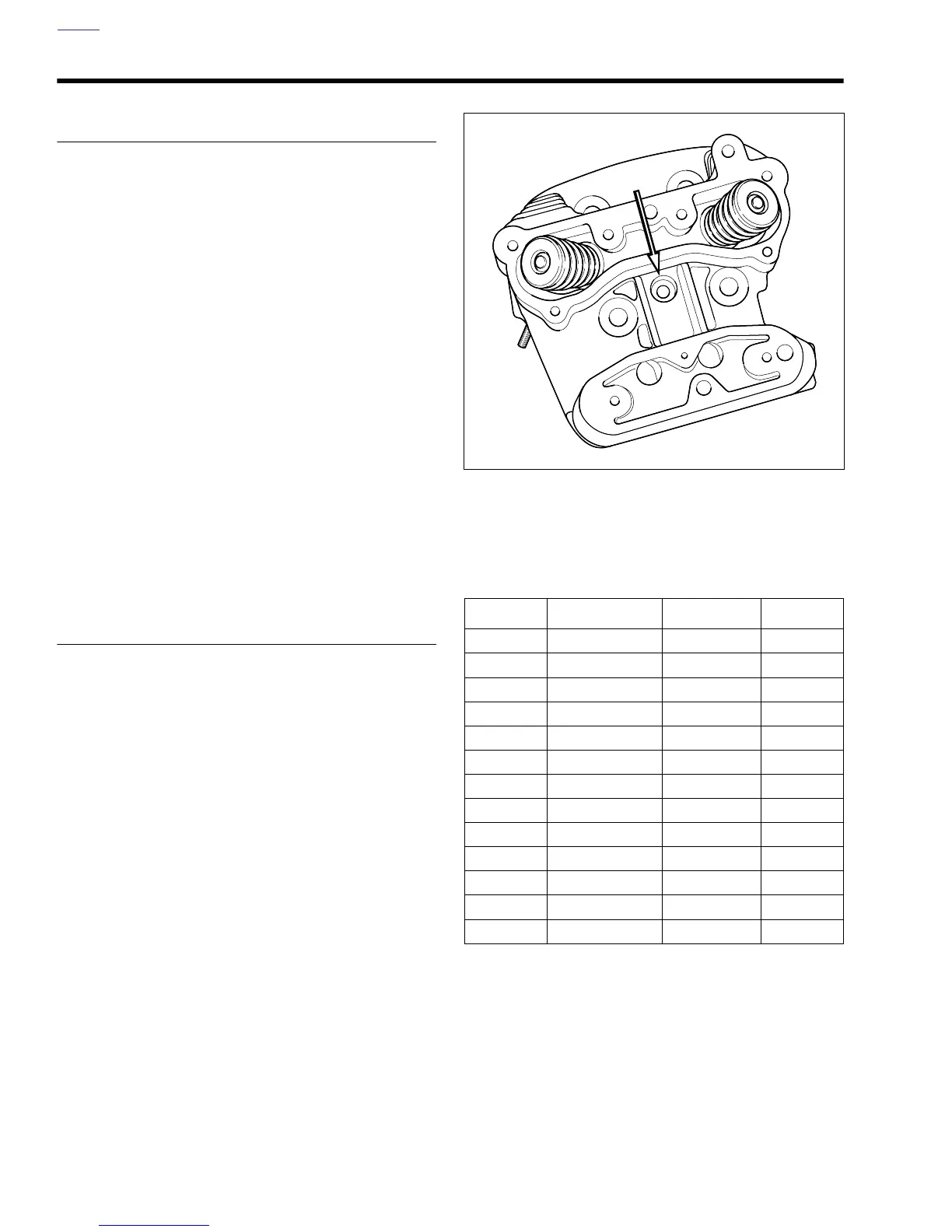
Figure 4-38. Location of Engine Temperature Sensor
in Rear Cylinder Head
Table 4-20. Engine Temperature
Sensor Specifications
VOLTS RESISTANCE TEMP °C TEMP °F
0.00 0 300 572
0.21 145 255 491
0.42 303 210 410
0.62 463 190 374
0.81 638 170 338
1.20 1042 150 302
1.59 1539 130 266
3.01 4991 85 185
4.43 25,647 40 104
4.63 41,295 25 77
4.83 93,759 10 50
4.88 134,200 0 32
4.93 232,414 -10 14
b0801x4x