2007 Buell Lightning: Appendix B B-5
HOME
DEUTSCH ELECTRICAL CONNECTORS B.2
GENERAL
Deutsch Connectors feature a superior seal to protect electri-
cal contacts from dirt and moisture in harsh environments.
The connector also provides superior pin retention.
See Figure B-8. This 12-pin connector illustrates the various
parts of the Deutsch connector. The following instructions
may be followed for all 2-pin through 12-pin Deutsch connec-
tors.
Socket housing:
alignment tabs and/or external latch, sec-
ondary locking wedge, internal seal, wire seal, seal pin.
NOTE
Seal pins or plugs are installed in the wire seals of unused pin
and socket locations. If removed, seal pins must be replaced
to maintain the integrity of the environmental seal.
Pin housing:
alignment grooves and/or external latch cover,
attachment clip, secondary locking wedge, wire seal, seal pin.
REMOVING/DISASSEMBLING
Attachment clips are attached to the pin housings of most
connectors. The clips are then attached to T-studs on the
motorcycle frame. T-studs give positive location to electrical
connectors and wire harness. Consistent location reduces
electrical problems and improves serviceability.
1. Push the connector to disengage small end of slot on
attachment clip from T-stud. Lift connector off T-stud.
2. Depress the external latch(es) on the socket housing
side and use a rocking motion to separate the pin and
socket halves. Two-, three-, four- and six-pin Deutsch
connectors have one external latch, while eight- and
twelve-pin connectors have two, both of which must be
pressed simultaneously to separate the connector
halves.
NOTE
With few exceptions, the socket housing can always be found
on the accessory side, while the pin side of the connector is
connected to the wiring harness.
REMOVING/INSTALLING SOCKETS
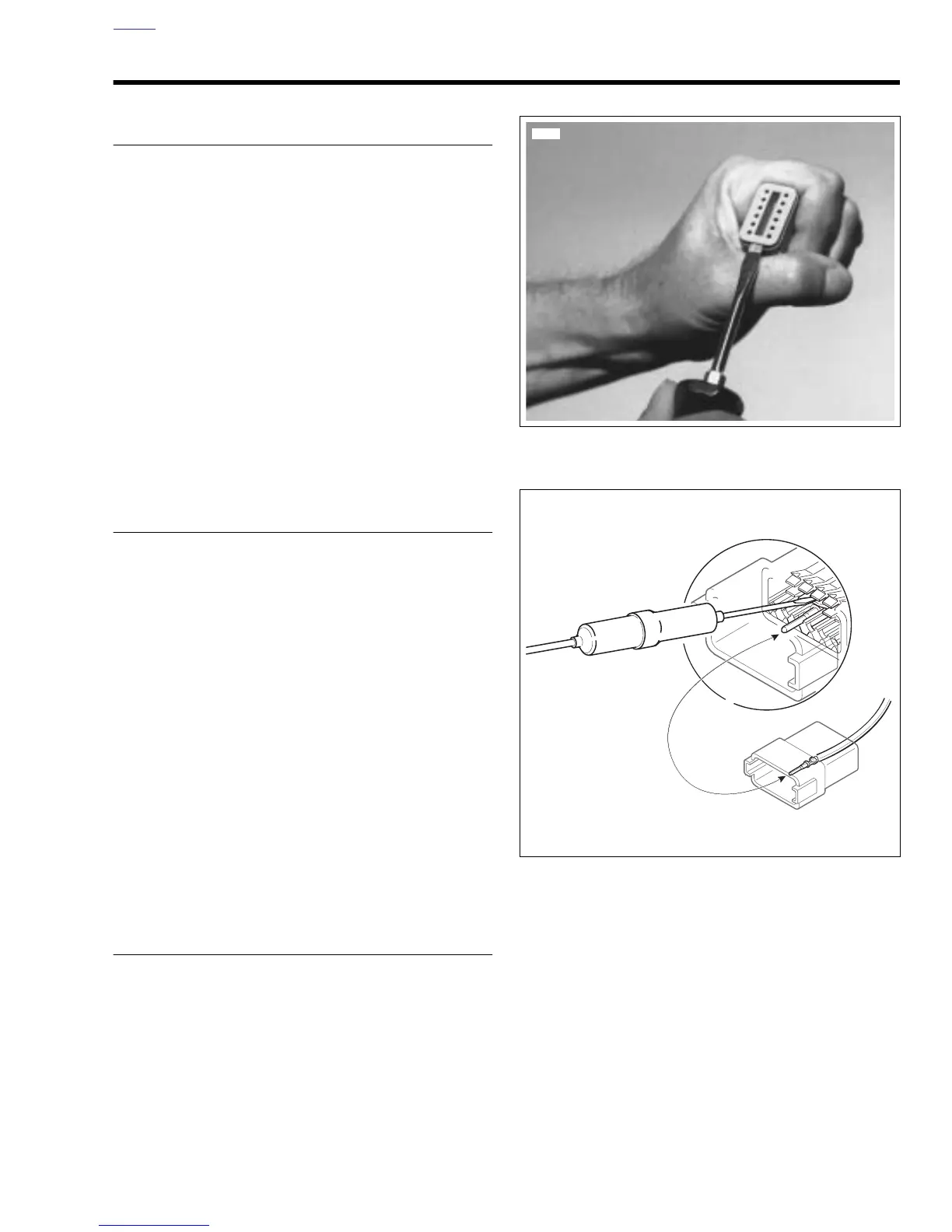
1. See Figure B-7. Remove the secondary locking wedge.
Insert the blade of a small screwdriver between the
socket housing and locking wedge inline with the groove
(inline with the pin holes if the groove is absent). Turn the
screwdriver 90 degrees to pop the wedge up.
2. See Figure B-8. Gently depress terminal latches inside
socket housing and back out sockets through holes in
rear wire seal.
NOTE
An ELECTRICAL TERMINAL CRIMP TOOL (Part No. HD-
39965) is used to install Deutsch pin and socket terminals on
wires. If
new
terminals must be installed, follow the instruc-
tions included with the crimping tool or see Crimping Instruc-
tions in this section.
3. Fit rear wire seal into back of socket housing, if removed.
Grasp socket approximately 1.0 in. (25.4 mm) behind the
contact barrel. Gently push sockets through holes in wire
seal into their respective chambers. Feed socket into
chamber until it “clicks” in place. Verify that socket will not
back out of chamber; a slight tug on the wire will confirm
that it is properly locked in place.
Figure B-6. Remove Secondary Locking Wedge
Figure B-7. Depress Terminal Latches/Back Out Pins