4-102 2007 Buell Lightning: Fuel System
HOME
ENGINE TEMPERATURE SENSOR 4.34
GENERAL
See Figure 4-82. The Engine Temperature Sensor (ET Sen-
sor), located in the rear cylinder head, monitors the engine
temperature close to the combustion chamber. In addition to
aiding the ECM in monitoring the operation of the engine, it is
also used to warn the operator of potentially damaging tem-
peratures by causing the CHECK ENGINE lamp to blink dur-
ing operation.
REMOVAL
1. Remove seat. See 2.44 SEAT.
1WARNING1WARNING
To prevent accidental vehicle start-up, which could
cause death or serious injury, disconnect negative (-)
battery cable before proceeding. (00048a)
2. Disconnect negative battery cable.
3. Remove intake cover assembly. See 2.38 INTAKE
COVER ASSEMBLY.
4. Remove air cleaner. See 4.44 AIR CLEANER ASSEM-
BLY.
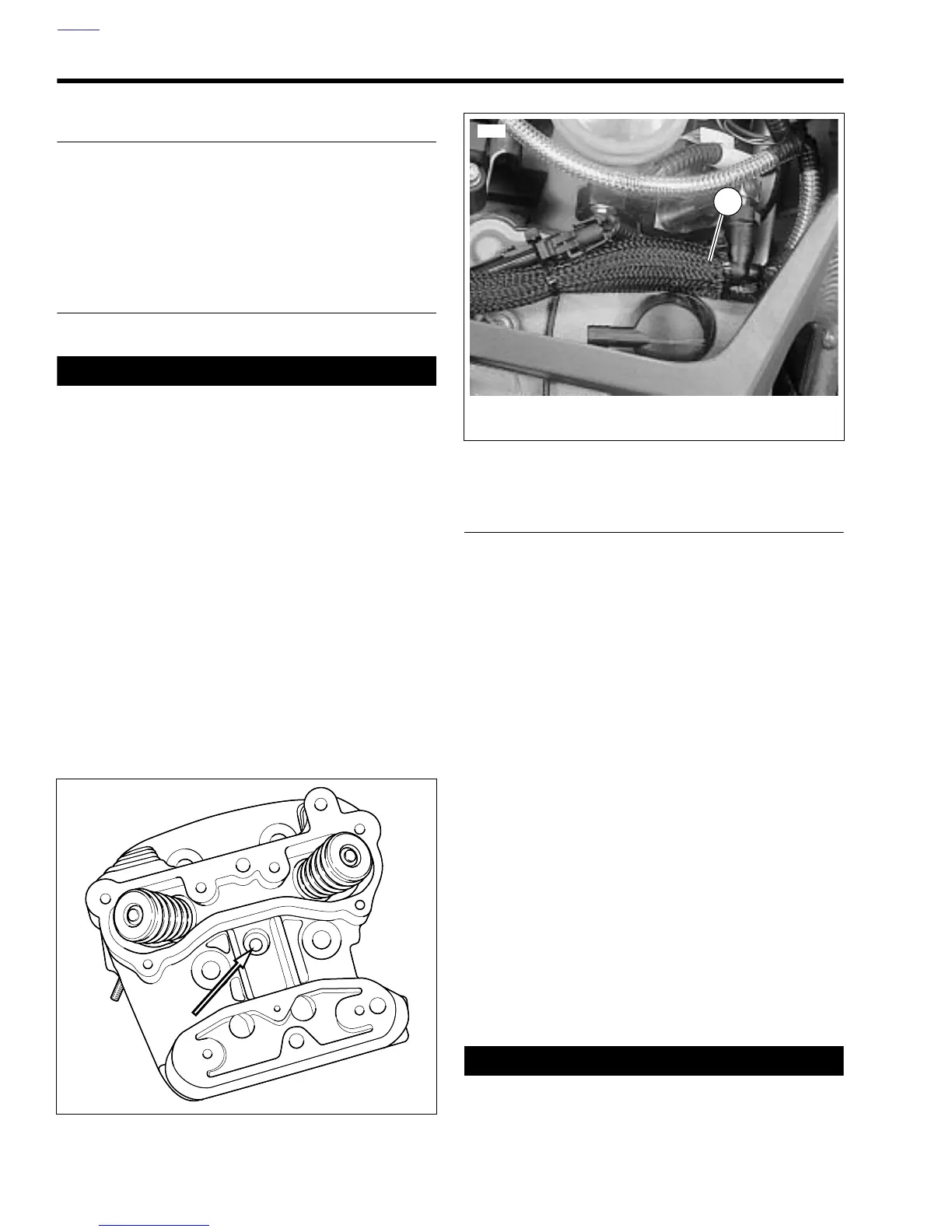
5. See Figure 4-83. Remove right upper tie bar fastener.
Rotate tie bar to provide access to sensor.
NOTE
Do not pull on engine temperature sensor wiring. Excess
strain to sensor wiring will cause sensor damage.
6. Unplug 1-place ET Sensor connector (1) [90] above rear
cylinder head.
7. Slide rubber boot up ET sensor wire.
8. Remove sensor from rear cylinder head using Snap-on
socket M3503B.
INSTALLATION
NOTE
Do not pull on engine temperature sensor wiring. Excess
strain to sensor wiring will cause sensor damage.
1. See Figure 4-82. Screw sensor into rear cylinder head.
NOTE
In next step, make sure wire is in cutout portion (slot) of
socket to prevent damage.
2. Secure sensor with Snap-on socket M3503B. Tighten ET
sensor to 120-168 in-lbs (13.6-19 Nm).
NOTE
Orient the rubber boot so the flat on the boot is towards the
left side of the motorcycle.
3. Push rubber boot down sensor wire towards cylinder
head until it seats in hole on top of ET sensor.
4. See Figure 4-83. Connect ET sensor 1-place connector
[90] to wiring harness.
5. Install right upper tie bar fastener. Tighten fastener to 25-
27 ft-lbs (33.9-36.6 Nm).
6. Install air cleaner. See 4.44 AIR CLEANER ASSEMBLY.
7. Install intake cover assembly. See 2.38 INTAKE COVER
ASSEMBLY.
8. Connect negative battery cable.
1WARNING1WARNING
After installing seat, pull upward on front of seat to be
sure it is in locked position. While riding, a loose seat can
shift causing loss of control, which could result in death
or serious injury. (00070a)
9. Install seat. See 2.44 SEAT.
Figure 4-82. Engine Temperature Sensor Location (rear
cylinder)
b0801x4x
Figure 4-83. Engine Temperature Sensor Connector [90]
Approximate Location
1. Engine temperature sensor connector [90]
(approximate location)
10557
1