2-32 2007 Buell Lightning: Chassis
HOME
INSTALLATION
NOTE
To avoid leakage, verify that gaskets, banjo bolt, hydraulic
brake line and master cylinder bore are completely clean.
1. See Figure 2-37. Connect brake line (14) to master cylin-
der (4) using two new copper washers (15) and a banjo
bolt (13) (metric). Loosely install bolt into master cylinder.
2. Route the brake line from the master cylinder to the cali-
per. See D.1 HOSE AND WIRE ROUTING for front brake
line routing.
3. Install and tighten P-clamp on inside of lighting module.
Tighten to 36-60 in-lbs (4-7 Nm). See 2.43 WIND-
SCREEN and 2.29 FRONT MODULES.
11WARNING1WARNING
Use only new copper crush banjo washers (See Parts
Catalog for Part No.) with D.O.T. 4 brake fluid. Earlier sil-
ver banjo washers are not compatible with D.O.T. 4 fluid
and will not seal properly over time. Failure to comply
may adversely affect braking ability and lead to brake
failure which could result in death or serious injury.
CAUTION
To avoid leakage, verify that gaskets, banjo bolt, hydrau-
lic brake line and caliper bore are completely clean.
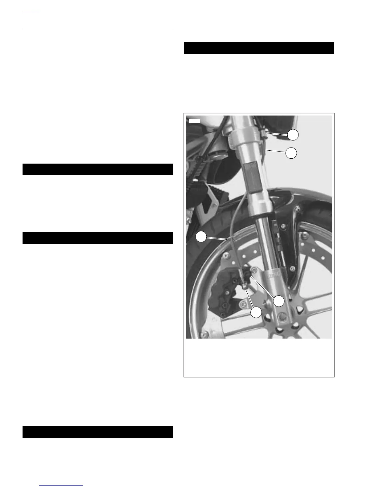
4. Install brake line to caliper.
a. See Figure 2-43. Install new copper washer, brake
line (2), new copper washer and wire form (3) onto
banjo bolt (5).
b. Finger tighten banjo bolt (5) onto front caliper being
careful not to pinch wire form (3) while tightening,
wire form should rotate around banjo bolt freely.
c. Twist brake line (2) into wire form (3) spiral and clock
wire form against bleeder valve (4).
5. Install and tighten p-clamp with fastener (1) on lower tri-
ple clamp to 36-60 in-lbs (4-7 Nm).
6. See Figure 2-37. Tighten master cylinder banjo bolt (13)
(metric) to 16-20 ft-lbs (22-27 Nm).
7. See Figure 2-43. Tighten brake caliper banjo bolt (5)
(metric) to 16-20 ft-lbs (22-27 Nm).
11WARNING1WARNING
After repairing the brake system, test brakes at low
speed. If brakes are not operating properly, testing at
high speeds can cause loss of control, which could
result in death or serious injury. (00289a)
8. Install bleeder valve if removed. Refill master cylinder
and bleed brakes. See 1.6 BRAKE SYSTEM MAINTE-
NANCE.
11WARNING1WARNING
Be sure that all lights and switches operate properly
before operating motorcycle. Low visibility of rider can
result in death or serious injury. (00316a)
9. Turn ignition key switch to ON. Apply brake hand lever to
test brake lamp operation. Turn ignition key switch to
OFF.
Figure 2-43. Front Brake Line
8429a
1. P-clamp
2. Brake line
3. Wire form
4. Bleeder valve
5. Banjo bolt
1
2
3
4
5