6-4
6. Loosen locknut (10). Turn chain adjuster screw (11) coun-
terclockwise (outward) to relax primary chain tension.
7. Remove four TORX screws with washers (1) and clutch
inspection cover (2). Remove and discard Quad ring (2)
from groove in primary cover.
8. Slide spring (3) with attached hex lockplate (4) from flats
of clutch adjusting screw (17).
9. Turn clutch adjusting screw (17) clockwise to release
ramp and coupling mechanism. As the adjusting screw is
turned, ramp assembly (7) moves forward. Unscrew nut
(5) from end of adjusting screw.
10. Remove hook of ramp from button to the rear of cable
end coupling (6). Remove cable end from slot in cou-
pling. Remove coupling and ramp assembly.
11. Remove screws which secure primary cover. Remove
cover and gasket. Discard gasket.
12. Remove and discard shift lever oil seal (14).
Primary Chain Adjuster
1. See Figure 6-2. Remove primary cover (1).
2. Remove locknut (2) from chain adjuster screw (3). Turn
adjuster screw out of threaded boss in primary cover.
3. Slide shoe (6) off plate (5) (shoe must be slid off plate
toward closed or blind side of shoe). Remove locknut (4)
and plate (5).
INSTALLATION
Primary Chain Adjuster
1. See Figure 6-3. If shoe (6) is badly worn, replace it or
adjust assembly.
2. Install plate (5) over top of chain adjuster screw (3).
Place spacer (7) over top of adjuster screw next to plate.
Secure plate and spacer to adjuster screw by threading
on locknut (4). Tighten locknut to 10-12 ft-lbs (14-16 Nm).
3. Place plate into slots at open end of shoe (6). Slide shoe
over plate until locknut at top end of adjuster screw is
against closed (blind) side of shoe.
4. Position adjuster inside primary cover (1) with closed
side of shoe against cover. Thread adjuster screw into
tapped boss at bottom of primary cover. At outside of
cover, install locknut (2) onto adjuster screw with nylon
sealing surface toward cover.
5. Install primary cover.
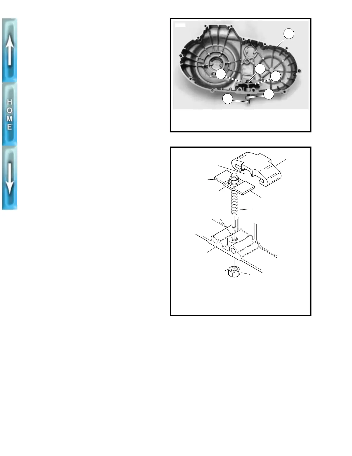
Figure 6-2. Removing Primary Chain Adjuster
Figure 6-3. Primary Chain Adjuster
1. Primary cover
2. Locknut (exterior)
3. Chain adjuster screw
4. Locknut (interior)
5. Plate
6. Shoe
3
3547
2
1
4
5
6
1. Primary cover
2. Locknut (exterior)
3. Chain adjuster screw
4. Locknut (interior)
5. Plate
6. Shoe
7. Spacer
b0133x6x
1
3
4
2
Threaded
boss
Open
side
6
Nylon sealing
surface
5
7