7-6
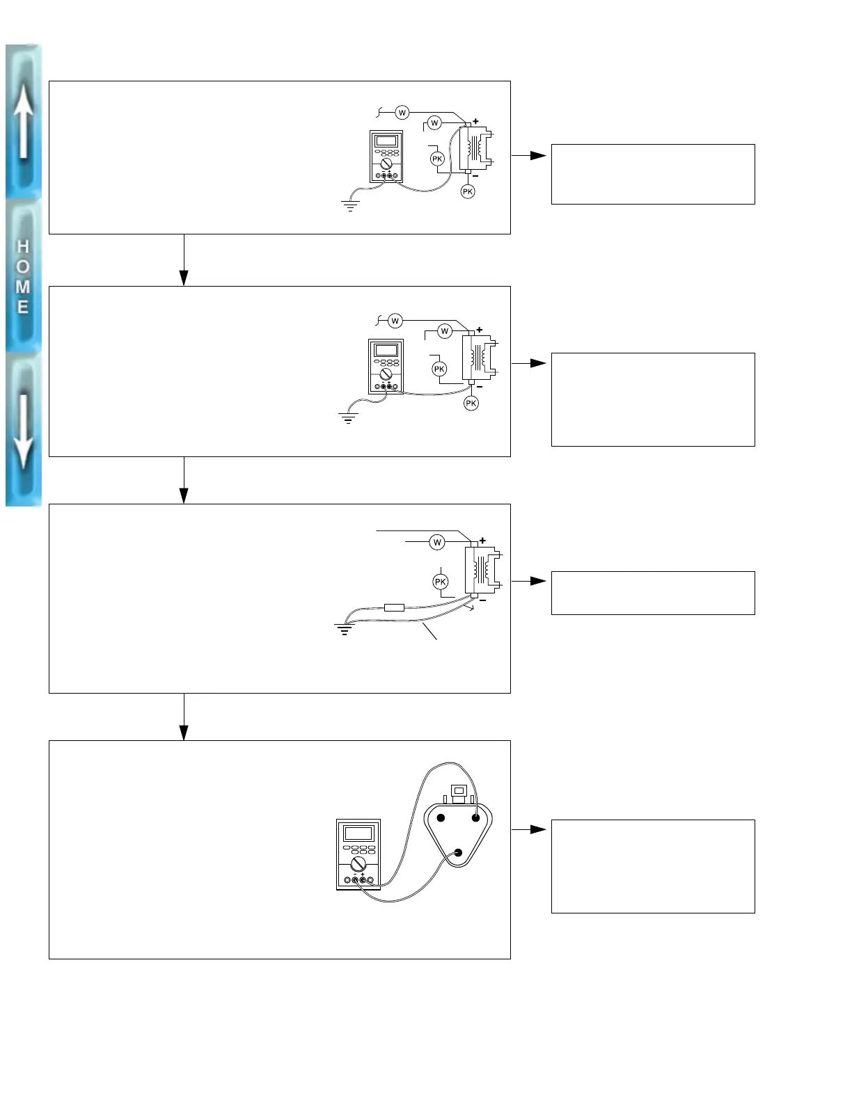
Continuous or No Spark at Plug
STEP 1
1. Ignition switch on.
2. Multimeter red wire to white wire terminal,
black wire to ground.
3. Meter should register 12 VDC
±
1.0 volt. If
meter is correct, proceed to STEP 2.
To tach
IF NO POWER
Check circuit breaker, ignition relay,
loose wires, switches.
b0077x7x
STEP 2
1. Remove pink (module) wire from coil
terminal.
2. Ignition switch on.
3. Multimeter red wire alternately to white
wire terminal and to pink wire terminal.
4. Meter should register 12 VDC at both
terminals. If meter is correct, proceed
to STEP 3.
IF NO POWER
Check coil resistance. See COIL
later in this section.
If resistance is OK check spark.
See STEP 3.
b0078x7x
STEP 3
1. Pink (module) wire disconnected.
2. Ignition switch on.
3. Jumper wire – connect capacitor wire to
pink wire terminal.
4. Connect both wires to common ground.
5. Momentarily touch ground wire to pink wire
terminal. When you remove the wire, there
should be a spark at plug. If spark occurs,
proceed to STEP 4.
Jumper
IF NO SPARK
Replace coil.
b0079x7x
STEP 4
1. Reconnect pink wire to coil.
2. Ignition switch on.
3. Disconnect sensor.
4. Connector from module–multimeter red
wire to red wire socket and multimeter
black wire to black/white pin. Should regis-
ter 12 VDC
±
0.5 volts. If meter is correct,
proceed to STEP 5.
BA
C
A. Green
B. Black/white pin
C. Red from module
IF NO POWER
Check module ground and power
wire to module for loose connec-
tions. See Resistance Test which
follows. Check spark, STEP 5.
x0043ax7x