1-31
ADJUSTMENT
1. See Figure 1-44. Remove outer cover pop rivets (1),
outer timer cover (2), inner cover screws (3), inner cover
(4) and gasket (5).
2. Loosen timer plate studs (6) just enough to allow sensor
assembly (8) to be rotated using a screwdriver in the
plate’s notch.
3. With timing light aimed into inspection hole, rotate sensor
assembly (8) until front cylinder advance timing mark is
centered in timing inspection hole.
4. Tighten timer plate studs (6).
5. Install gasket (5), inner cover (4), inner cover screws (3),
timer cover (2) and new outer cover rivets (1).
6. Remove TIMING MARK VIEW PLUG from timing inspec-
tion hole. Install hex socket timing plug.
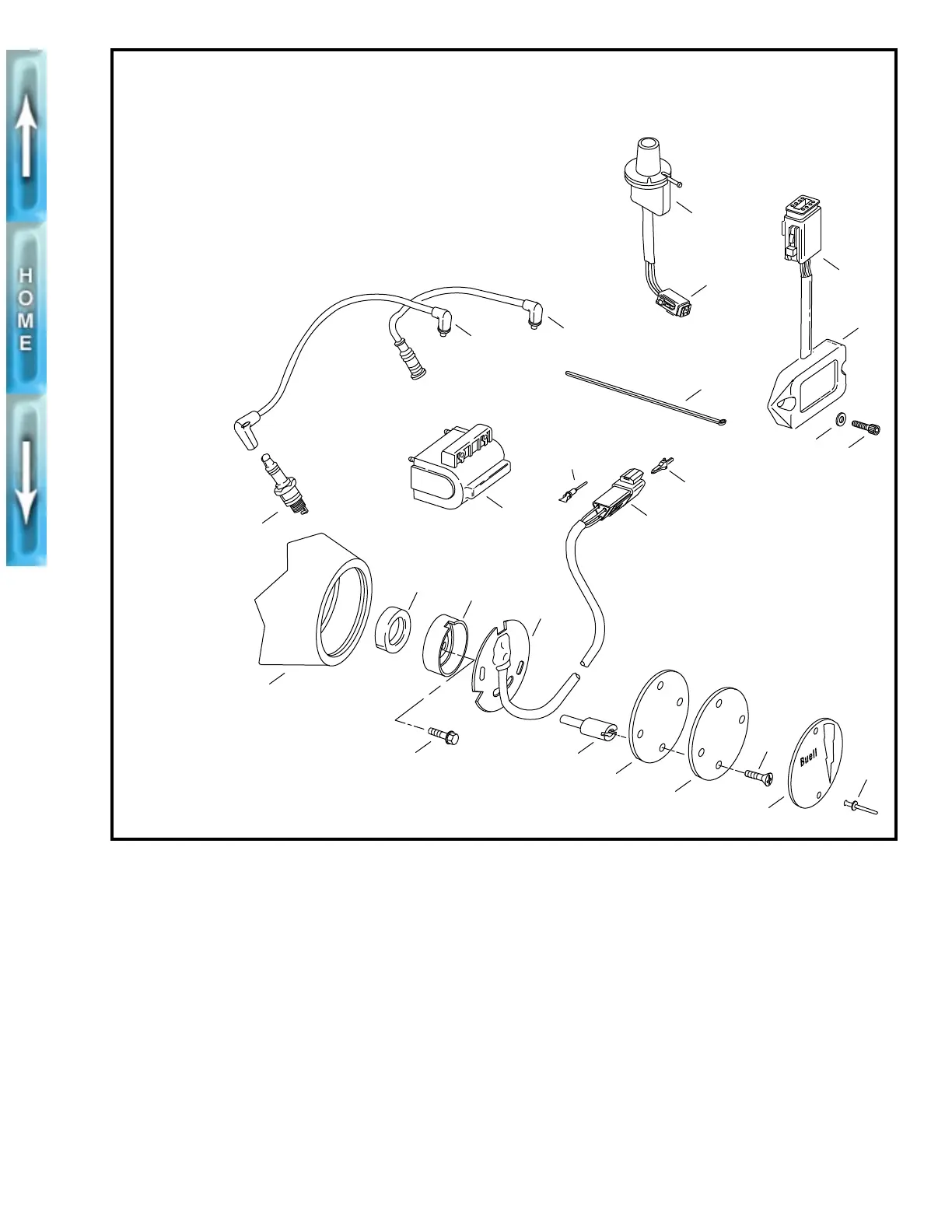
Figure 1-44. Ignition System Components
1
2
1. Pop rivet (2)
2. Timer cover
3. Screw (2)
4. Inner cover
5. Ignition gasket
6. Timer plate stud (2)
7. Bolt
8. Sensor assembly
9. Trigger rotor
10. Seal
11. Gearcase cover
12. Spark plug (2)
13. Ignition coil
4
5
6
7
11
12
15
14
13
20
21
19
17
16
23
22
18
3
8
9
10
14. Front spark plug cable
15. Rear spark plug cable
16. V.O.E.S. connector [P7]
17. V.O.E.S.
18. Cable strap
19. Terminal pin
20. Timer connector [P16]
21. Secondary lock
22. Ignition module connector [P10]
23. Ignition module
24. Washer (2)
25. Screw (2)
24
25
b0223x7x