INTELLIDOX DOCKING MODULE USER MANUAL || ASSEMBLE MODULES
BW TECHNOLOGIES BY HONEYWELL PAGE 15 OF 103
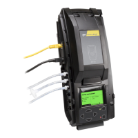
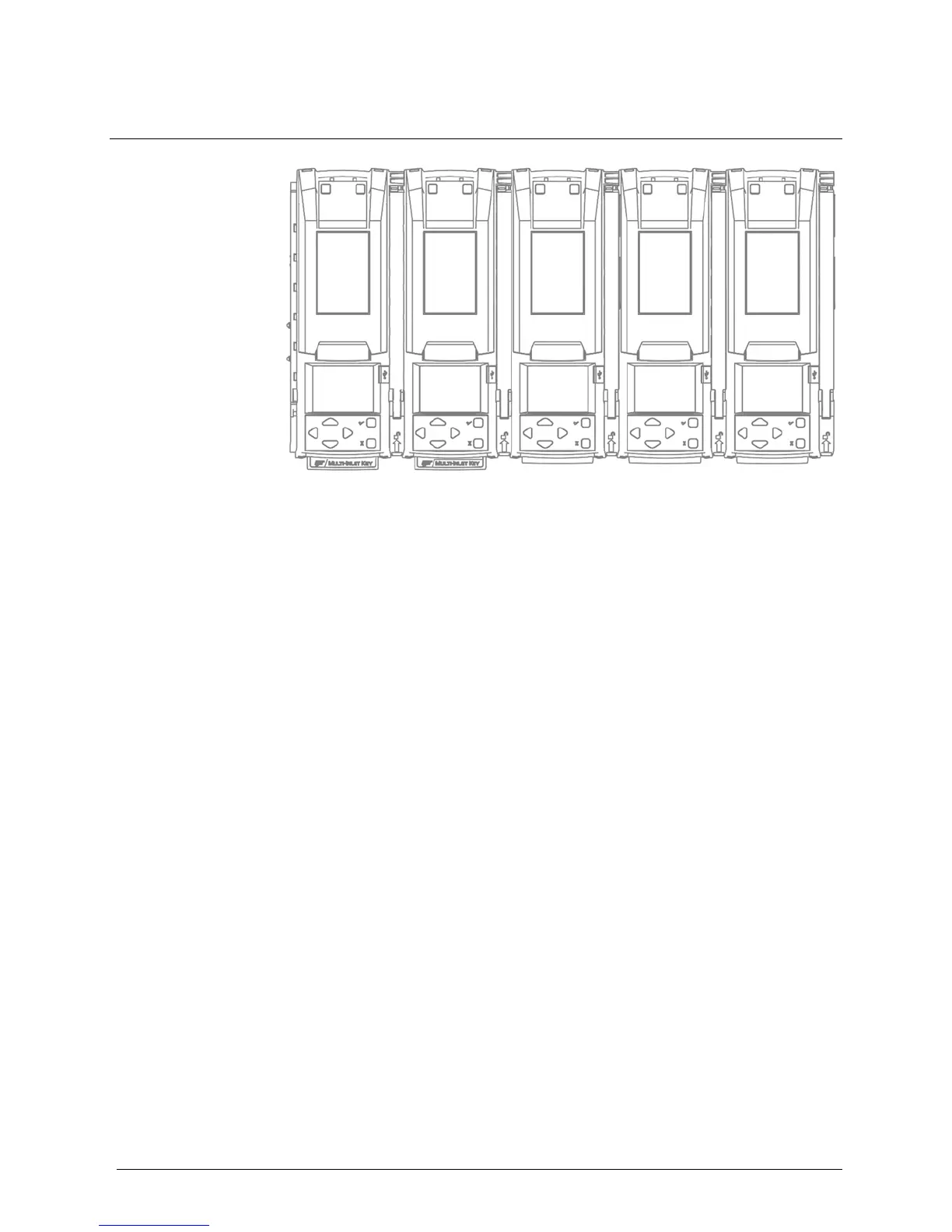
Work Plan: Assemble Gangs of up to Five Connected Modules
Up to five modules may be connected to form a gang. Connected modules share the
power supply, exhaust tubing, inlet filter, connected test gas cylinders and network
connection. Follow these steps to assemble and prepare gangs of up to five connected
modules for first use:
1. Place the modules and component parts on a clean, dry work surface.
2. Verify that the appropriate inlet keys are inserted. Replace the inlet keys if necessary.
For more information, see Inlet Keys on page 9.
3. Assemble the stand or mount the module on a wall or DIN rail if necessary. For more
information, see:
Assemble the Stand on page 16.
Mount on a Wall on page 18.
Mount on Parallel DIN Rails on page 22.
4. Connect up to 5 modules. For more information, see:
Connecting Modules on page 17.
Mounting Connected Modules on a Wall on page 20.
5. Prepare the connected modules for use. For more information, see Prepare Modules
for Use on page 25.
1. Attach the end plate to the last module in the gang. See Attach the End
Plate on page 26.
2. Connect an inlet filter to the purge inlet on the first module in the gang. For
more information, see Connect the Inlet filter on page 28.
3. Insert an inlet plug into each unused inlet on the first module in the gang. For
more information, see Insert the Inlet Plugs on page 29.
4. Connect the exhaust tubing to the first module in the gang. For more
information, see Connect the Exhaust Tubing on page 27.
5. Connect the power to the first module in the gang.
6. Connect to a network. See Connect the Module to a Network on page 31.
6. Connect the calibration gas cylinder or cylinders, and then configure the gas inlets.
For more information, see Connect a Calibration Gas Cylinder on page 35 and
Configure Gas Inlets on page 41.