EasyManua.ls Logo

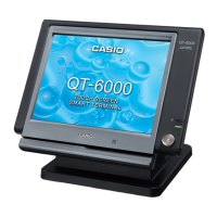
Casio QT-6000 - Block Diagram; Circuit Explanation

Casio QT-6000
154 pages
To Next Page IconTo Next Page
To Previous Page IconTo Previous Page
Loading...
— 51 —
option
iButton Probe
+19V
12.1inch TFT LCD UNIT
Touch Panel
CFL INVERTOR unit
Init
CUSTOMER DISP. SYSTEM
OPTIONAL REMOTE
+5V Supply
OPTIONAL Hand Held Scanner
iButton
FROM
EtherNet 1
iButton
LCDC
CF CARD
CF card I/F
CardBus
CPU
Power Supply for CFL
Wireless LAN CARD
SPEAKER
SW
CFL
CARDBUS card I/F
COM1
DSUB9pin
Battery
main pcb
+5V Supply
COM2
SIGNAL ONLY
Disp On/Off
SDRAM
E820-1
MCR
I/O ctrl.
G/A Sound
BGA256pin
BGA90pin
EtherNet
MODEM or PC
COM4~6
DSUB9pin x3
SPEAKER Out
MIC in
Green
DL-****
POWER CORD
DSUB9pin
DSUB9pin
AC adaptor unit type
(LPS)
Casio Drawer2
HUB
SPEAKER OU
SIGNAL ONLY
CAT.5 UTP cable
DL-****
FPC
harness FFC
Optional Printer, etc.
MIC in
POWER SUPPLY UNIT
Power Status
Casio Drawer1
POW SW
COM3
Built-in MIC
SW
LED
8. CIRCUIT EXPLANATION
8-1. BLOCK DIAGRAM

Table of Contents

Other manuals for Casio QT-6000

Related product manuals