— 76 —
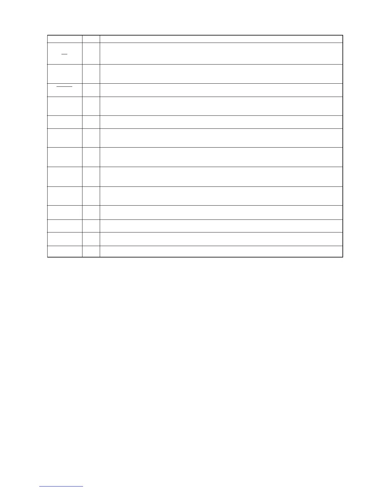
PIN NAME I/O DESCRIPTION
Oscillator connection pins. When external clock is used, input clock into XT pin and leave XT pin open.
Outputs sampling frequency selected at recording or playback.
VCK pin is used as a synchronizing signal when external ADC or DAC is used.
When this pin is “L” level input, the LSI is initialized.
Pins for testing. Set the pins to “L”.
Analog circuit signal ground output pin.
Inverting input pin for built-in OP amplifier. Noninverting input pin is connected to SG (Signal Ground)
internally.
MOUT is the output of internal OP amplifier to MIN, and LOUT is to LIN.
Left analog output pin from built-in LPF. This is the output pin of playback wavefroms, and is connected to
the amplifier for driving speakers.
Right analog output pin from built-in LPF. This is the output pin of playback wavefroms, and is connected to
the amplifier for driving speakers.
Digital power supply pin. Insert a minimum 0.1 mF bypass capacitor between this pin and DGND pin.
Digital GND pin.
Analog power supply pin. Insert a minimum 0.1 mF bypass capacitor between this pin and AGND pin.
Analog GND pin.
XT
XT
VCK
RESET
TEST0
TEST1
SG
MIN
LIN
MOUT
LOUT
AOUTL
AOUTR
DVDD
DGND
AVDD
AGND
I
O
O
I
I
O
I
O
O
O
—
—
—
—

 Loading...