CESSNA
SECTION
7
MODEL
2088
(675
SHP) AIRPLANE AND SYSTEMS DESCRIPTION
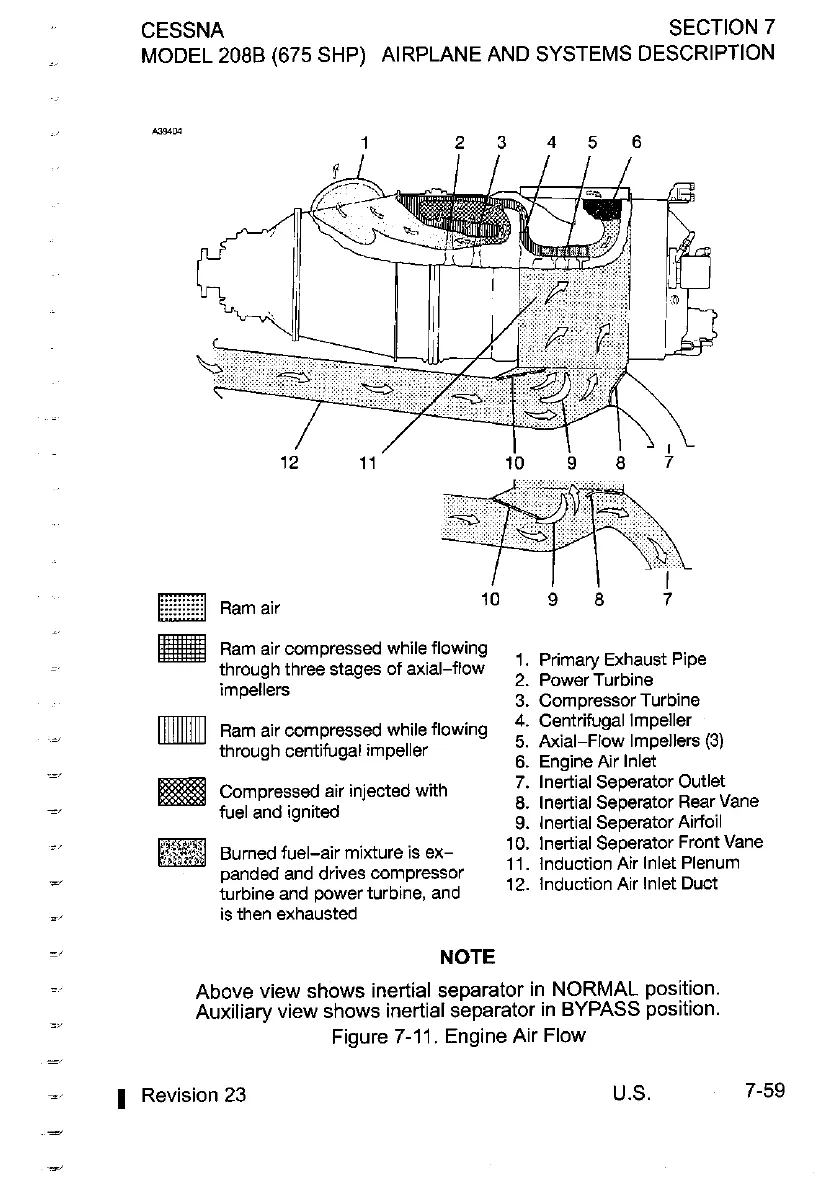
Ram air compressed while flowing
~,
through three stages of axial-flow
2.
1.
Primary
Power
Turbine
Exhaust Pipe
impellers
3.
Compressor Turbine
[IIIIIIIIIl
Ram air compressed while flowing
4.
Centrifugal Impeller
=,
through centifugal impeller
5.
Axial-Flow Impellers
(3)
...,
6.
Engine Air lnlet
-
Compressed air injected with
7.
lnertial Seperator Outlet
=,
fuel and ignited
8.
lnertial Seperator Rear Vane
9.
lnertial Seperator Airfoil
:,
Burned fuel-air mixture is ex-
10.
lnertial ~eperator Front Vane
11.
Induction Air lnlet Plenum
-
panded and drives compressor
12,
Air
Duct
turbine and power turbine, and
=,
is then exhausted
=,
NOTE
=,
Above view shows inertial separator in NORMAL position.
:,
Auxiliary view shows inertial separator in BYPASS position.
Figure
7-11.
Engine Air Flow
=~
-'
1
Revision
23
U.S.
7-59