11-2
Chadwick-Helmuth Company, Inc.
Chapter 11
- Model 8 520C Signal Selector
11.2 Signal Selector Operation
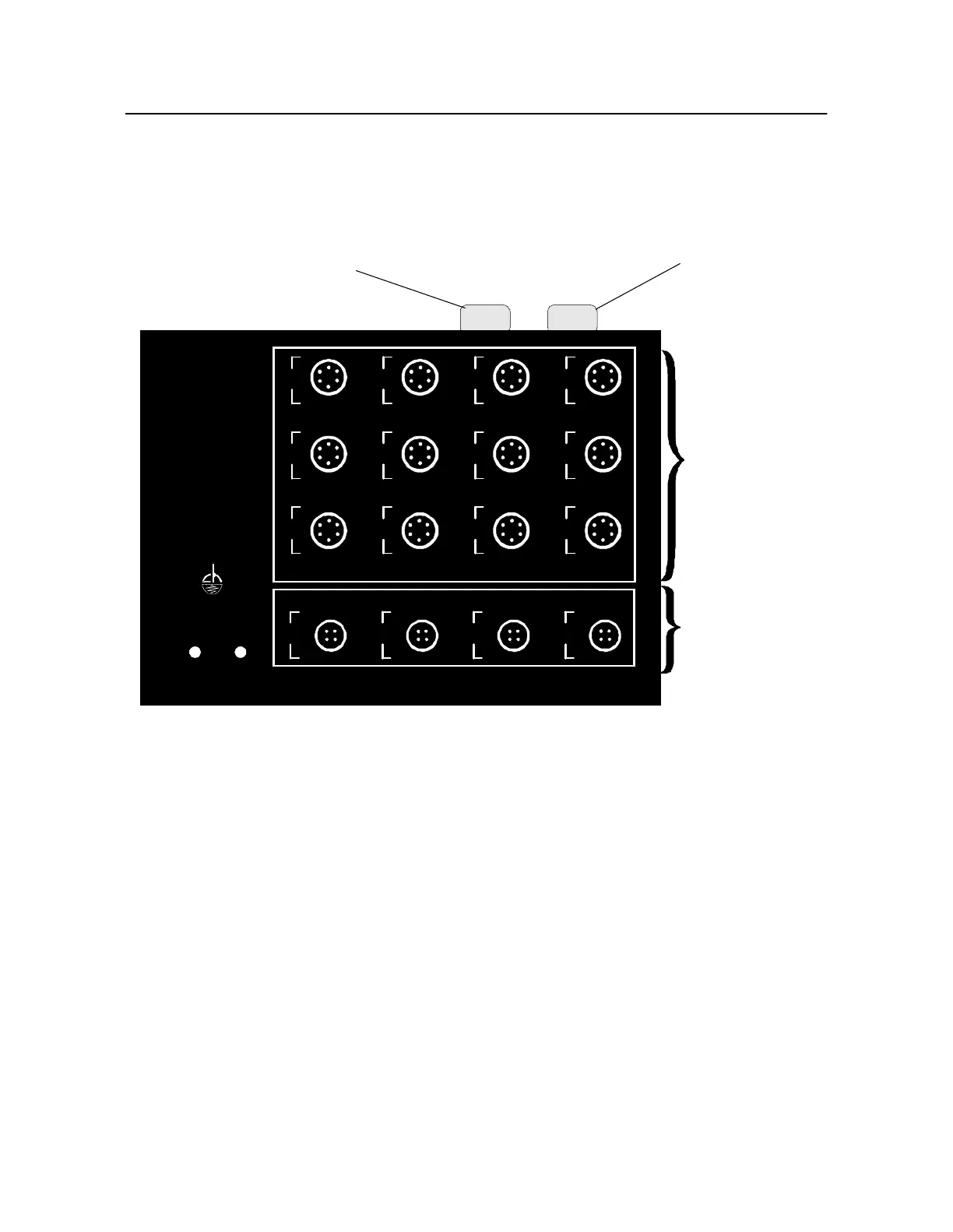
The diagram below (Figur e11-1) shows an illustration of the Signal Selector.
Figure 11-1. Signal Selector
Signal Selector signal channels are labeled on the front panel of the unit. Channels No.1 t hrough 12
accept velocimeter inputs, and cha nnelsA t hroughD accept magnetic pi ckup, Model11800 FasTrak
Optical Tracker, or Photocell inputs. Magnetic pickup inputs can come from the Model303 Magnetic
Pickup or any compatible single-interrupter magnetic pickup equipment. Communication with the
SIGNAL
SELECTOR
CHADWICK-HELMUTH
E L M O N T E , C A L I F O R N I A
MAGNETIC PICKUP/PHOTOCELL CHANNELS
1
2
3
4
5
6
7
8
9
10
11
12
AB
C
D
VELOCIMETER CHANNELS
VELO
SHORT
POWER
MODEL 8520C
CN_8520..DRW
VIBRATION
SIGNAL INPUTS
AZIMUTH
SINGAL INPUTS
8500C/C+
INTERFACE
CONNECTOR
DC POWER
CONNECTOR