2-4
Chadwick-Helmuth Company, Inc.
Chapter 2
- Overview and Basic Theory
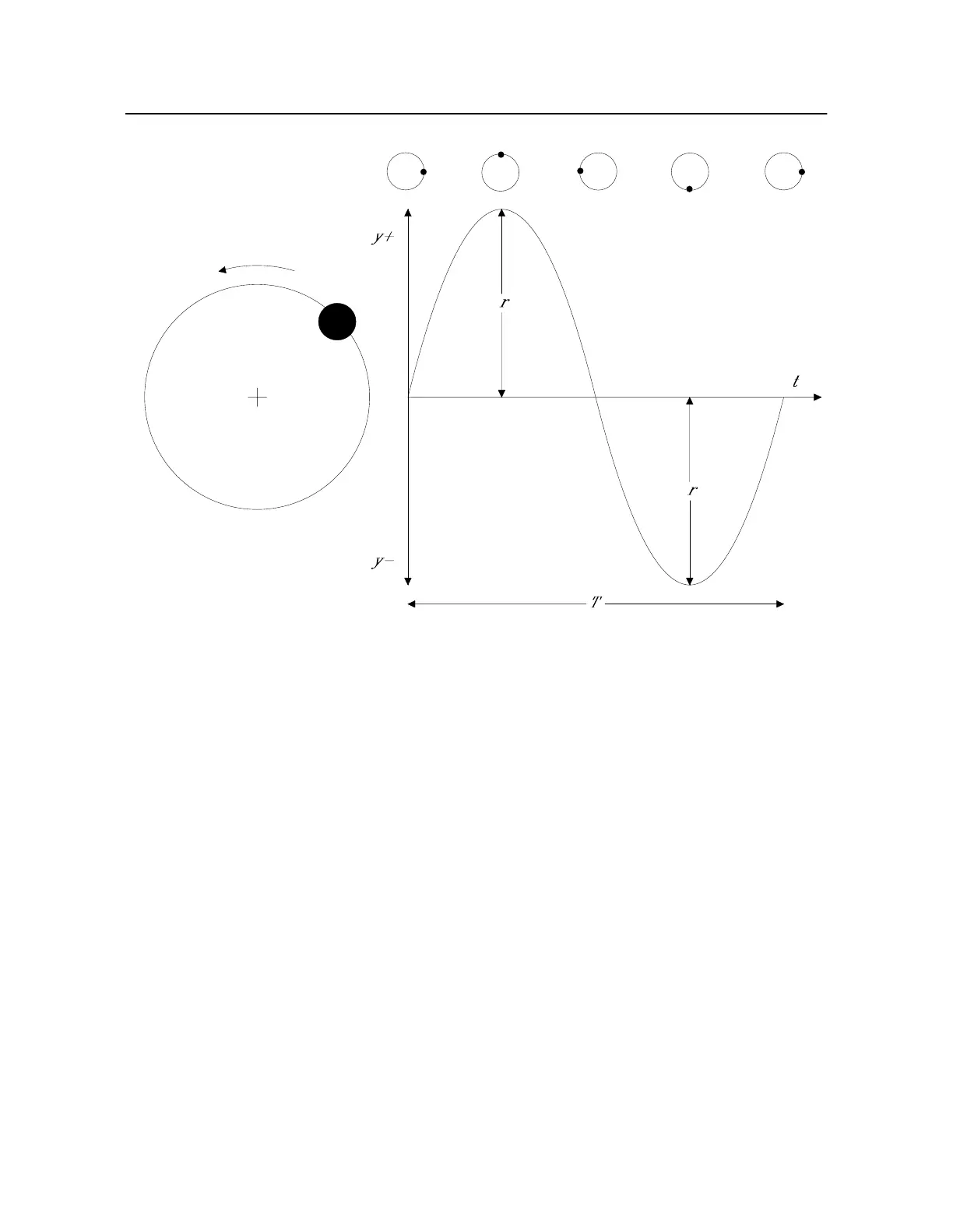
Figure 2-3. Displacement in an Imbalanced Rotor
The plot in Figur e2-3 actually describes a simple harmonic oscillator (sine curve) with time period
T
and frequency
f
, whose displacement,
y
, may be described mathematically by the equation
In this equation,
r
is the amplitude of vibration and
θ
the phase angle.
0
yr
θ
sin=
()
d