Balance Measurement
Mode l8500C/8500C+ Operators Manual
5-11
5.4.2 Magnetic Pickup/Photocell Measurement
The procedures for magnetic pickup or Photocell balance measurement are nearly identical, except fo
the input devices employed. The Photocell kit requires the installation of a retro-reflective target on the
root of the target blade, whereas the magnetic pickup requires the installation of a magnetic interrupter
on the target rotor. Put the 8500C/C+ into the Balance mode and make sure the balance type is set to
Photocell
or
Mag Pickup
, whichever applies. With the rotor system running at the appropriate speed,
press
START
. As in a Strobex balance, the 8500C/C+ attempts to acquire a vibration signal by locking
onto the pickup pulse at the designated balance frequency.
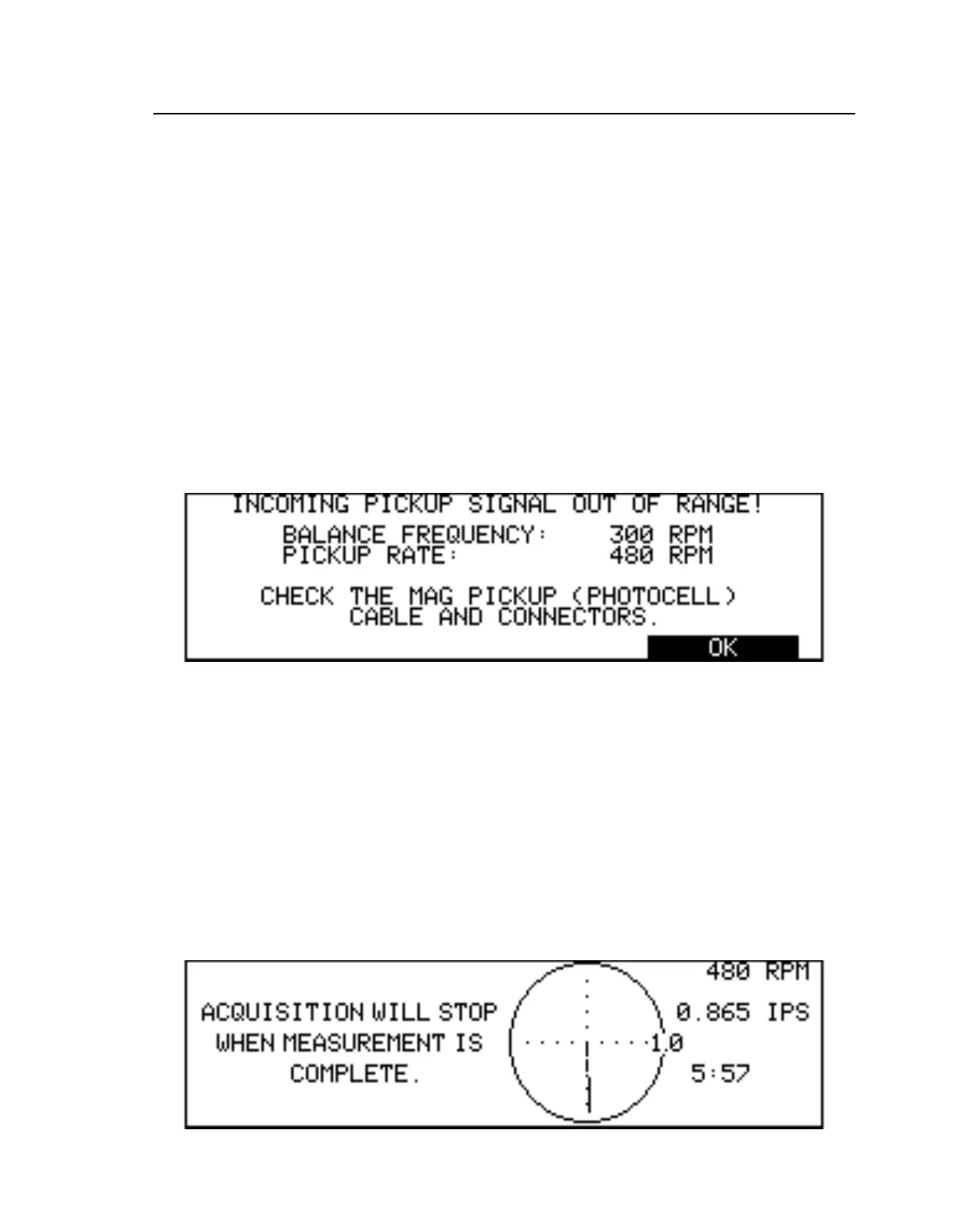
If no azimuth pulse is found at the balance frequency, the measurement terminates and an error
message is displayed (Figu re5-9). At this point, verify that the magnetic pickup/Photocell cables are
correctly connected, and that the devices themselves are correctly installed and in good working order.
You may also wish to verify that the designated balance frequency is within range of the actual
vibration signal. To do this action, take a spectral frequency plot via the
SPECTRU
key. The current
magnetic pickup rate is always displayed on the Status screen. Display this screen by pressing the
STATUS
key (see Chapter 9 “Status Screen Operation”).
Figure 5-9. Magnetic Pickup/Photocell: No Synchronization Signal Error
If a vibration signal is acquired, the 8500C/C+ displays a graphic representation of an analog phas
meter, a four-quadrant circle whose radius delimits a maximum vibration amplitude (see Fi gure5-10
on pa ge5-11). During the course of the measurement, a line vector is drawn from the origin and
continuously updated. Its magnitude represents the current vibration amplitude, and the central angle
subtended by it and the azimuth represents the current phase angle. Numerical values for the current
frequency, vibration amplitude, and phase are continuously displayed and updated.
If the auto-stop mode has been selected (see Se ction5.3.5 “Auto/Manual Stop” on pag e5-8), th
8500C/C+ automatically completes the measurement itself and displays the computed balanc
solution. If manual stop mode has been selected, wait for the vector to stabilize, then press
STOP
to
terminate the measurement and generate the balance solution. Again, the vector need not b
completely stationary to obtain an accurate solution.
Figure 5-10. Magnetic Pickup/Photocell Phase Meter Display