Signal Selector Operation
Mode l8500C/8500C+ Operators Manual
11-3
8500C/C+ is by a three-wire RS-232 connection (receive data, transmit data, and ground), and
employs an asynchronous serial interface with the following specificat ions: 96 00baud, 8data bits,
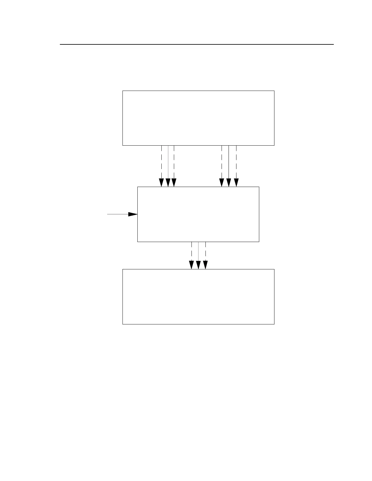
1 stop bit, no parity. See Fi gure11-2 below for details.
Figure 11-2. Model 8520 System Block Diagram
CAUTION: The Signal Selector only operates from a 2 8Vdc power supply. Plugging th
unit into a power source other than 2 8Vdc may cause severe damage.
Rotor System
Under Test
Model 8520C
Signal Selector
Model 8500C/C+
Balancer/Analyzer
28 VDC
Mag Pickup/Photocell
(up to 4)
Velocimeter
(up to 12)
Vibration signal
Pickup signal
Communications
28 VDC