2-12
Chadwick-Helmuth Company, Inc.
Chapter 2
- Overview and Basic Theory
2.3.2 Analog Subsyste
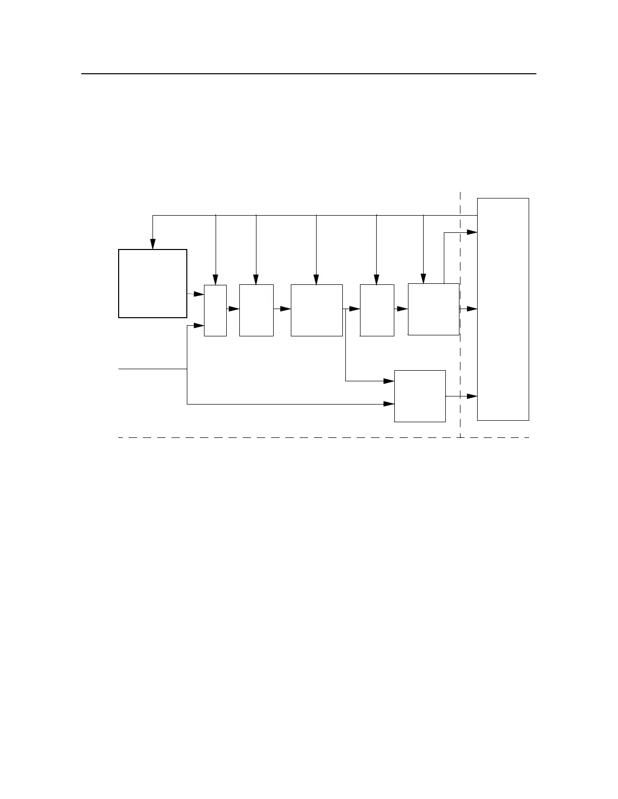
The analog subsystem reads analog input signals directly from the velocimeter or waveform generator,
filters them, samples them, and converts them to digital form through the analog-to-digital converter
(see Figur e 2 -9 below). The timing controller provides programmable clock signals that synchronize
this process. The digitized data are output to the microprocessor over the system bus where they are
stored in memory for analysis and display by the executive software.
Figure 2-9. 8500C/C+ Analog Subsystem Block Diagram
The analog subsystem includes a high-performance antialiasing filter to reduce spurious signals
introduced by the sampling process. A variable gain stage in the analog input signal path amplifies the
analog signal so that a high signal-to-noise ratio can be maintained over a wide dynamic range of
signal amplitudes. The gain is under program control and is set by the microprocessor through a
digital-to-analog converter. The on-board waveform generator provides known reference signals fo
calibration verification and test of the analog subsystem. A multiplexer selects either the velocimeter
input or the internal waveform generator as the input to the analog signal path. Finally, a clip detector
circuit ensures that no input signal amplitudes exceed a fixed reference voltage level.
For a detailed functional description of the 8500C/C+’s system architecture, see t he Model8500C/C+
System Maintenance Manual.
Auto-calibration
Test Waveform
Generator
Mux
Programmed
Gain
A/D
Clip
Detector
Vibration
Sensor Input
Bus
Interface/
Timing
Controller
Analog Board
Digital Board
Converter
Filter
Anti-
Alias
Filter
Anti-
Alias
Stage 1 Stages 2-5