System Architecture
Mode l8500C/8500C+ Operators Manual
2-11
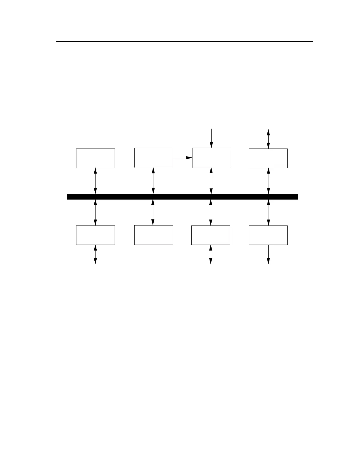
The microprocessor controls the entire system by communicating with the other blocks over the
system bus. Instructions and data used by the microprocessor are stored in memory. The memory block
itself is divided into the following sections:
• Program memory in the form of the read-only memory (ROM) that stores the system's software
• Temporary data memory in the form of dynamic random-access memory (DRAM
• Permanent data memory in the form of nonvolatile static RAM
Figure 2-8. 8500C/C+ Digital Subsystem Block Diagram
The timing controller is the system timing master. It generates the timing signals used to control majo
functions, such as analog-to-digital conversion, external synchronization, and strobe triggering. Th
timer drives the Strobex trigger by connecting to it through an opto-isolator at the strobe interface.
Timer counters are completely under program control, and the microprocessor communicates with
them over the system interface.
The serial input-output (I/O) block controls the various serial interfaces, as well as the clock interface
and a portion of the analog data acquisition interface. The clock interface communicates with
dedicated real-time clock that maintains the system date, day, and time. The disk controller block
mediates data flow between the rest of the system and the 8500C/C+’s 3.5-in. floppy disk drive. The
keyboard controller block reads keyboard input through the keyboard interface, and the display
controller block directs the liquid-crystal display (LCD) output through the display interface.
Micro-
Processor
Timing
Controller
Controller
Parallel
I/O
Acquisition
Serial I/O
Display
Control
Operator
Display
Operator
Keypad
Sensor
Input
Printer
Unit
Disk Unit
System
Bus
Memory