2-6
Chadwick-Helmuth Company, Inc.
Chapter 2
- Overview and Basic Theory
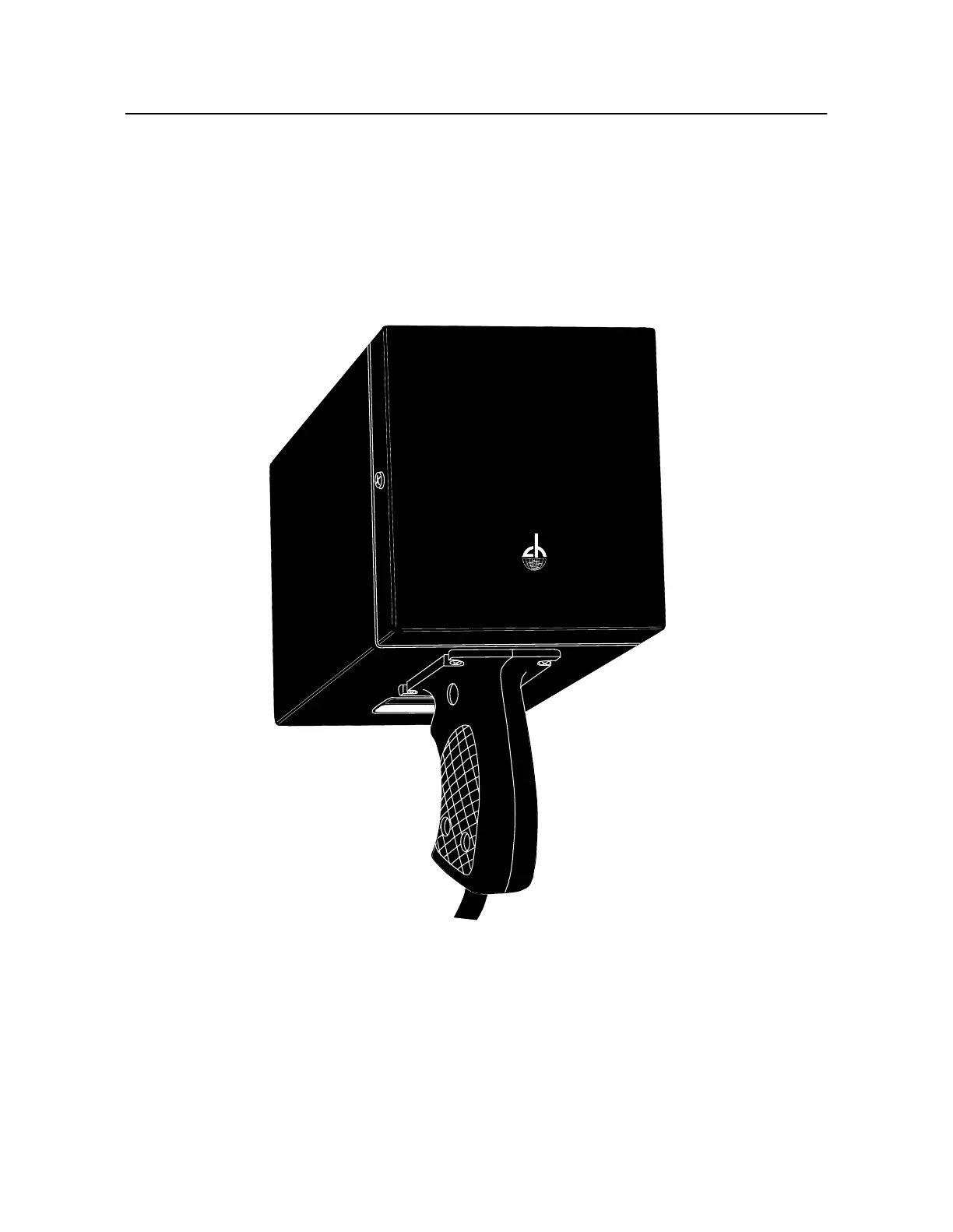
In one approach, the Balance Frequency is used to time a one-per-revolution triggering pulse to th
Chadwick-Helmuth Mode l 1 35-M12 Strobex Tracker (see Fi gure2-5). The Strobex flashes a
stroboscopic light with each trigger, and if it is aimed at a special retro-reflective target attached to the
spinning rotor, the target appears frozen at some angular position. This angular position indicates th
exact location of the mass imbalance. The 8500C/C+ can modulate the Strobex trigger so you can
visually move the target toward the rotor's reference azimuth. When the two points converge, the
8500C/C+ fixes the exact angular position and amplitude of vibration then computes the balance
solution.
Figure 2-5. Strobex Strobe Tracker
The Strobex is one way to locate a lateral mass imbalance. You may also use the Chadwick-Helmuth
Mode l3030 Magnetic Pickup and interrupter or Chadwick-Helmuth Photocell System and reflectiv
target to generate a one-per-revolution reference signal for the spinning rotor. If the interrupter or
reflective target has been secured to a known point on the spinning rotor, the 8500C/C+ can compare
this signal against the velocimeter output to compute the angular position of the out-of-balance
element.
STROBEX
MODEL 135M-12
CHADWICK HELMUTH
E L M O N T E , C A L I F O R N I A