6-4
Chadwick-Helmuth Company, Inc.
Chapter 6
- Blade Track Observation
6.4 Performing a Visual Track
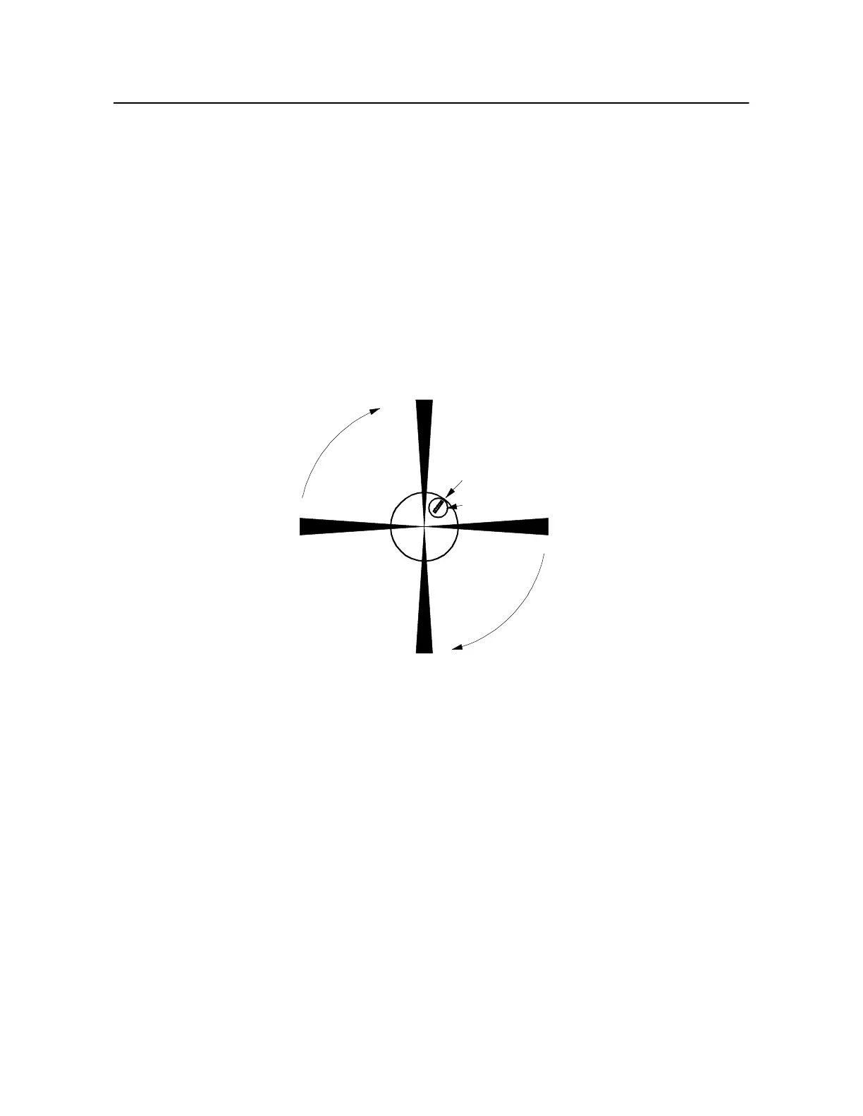
A visual track illuminates targets on the rotating blade tips and fixes their relative positions. The lead
blade in this configuration is called the master or target blade. This is a blade whose orientation to the
source of the Strobex trigger (Mode l3030 Magnetic Pickup or Photocell System) is always known.
Typically, it is designated as that blade which is located at the front of the aircraft when the interrupter
trips the magnetic pickup or when the retro-reflective target passes in front of the Photocell (see
Figur e6-3).
The master blade can usually be found on the schematic drawing that is displayed when the
CH ARTINFO
soft key is pressed in Balance mode (see Sect ion5.2.3.6 “Displaying Chart
Information” on page 5 -6).
Figure 6-3. Sample Rotor With Four Blades
6.4.1 Initiating a Visual Track
Visual tracking requires the installation of either a magnetic pickup and interrupter or Photocell and
reflective target. The Strobex must also be connected to the 8500C/C+ through the dedicated adapter.
In addition, special reflective targets must be installed on the blade tips according to the aircraft
manufacturer's directions. Connect the Strobex and power/signal input cables to the 8500C/C+ and
check that they are correctly secured to their connectors at the rear of the 8500C/C+. All cables must
be neatly tied and dressed, and the appropriate signal input device, Photocell or magnetic pickup,
correctly mounted and in good working order. Finally, bring the aircraft up to speed in the desired
M
4
3
2
Interrupter
Magnetic Pickup