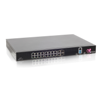
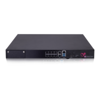
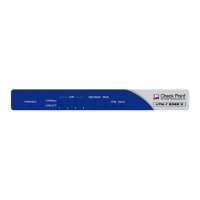
The UTM-1 Edge X Series and UTM-1 Edge W Series
16 Check Point UTM-1 Edge User Guide
Network Requirements
• 10BaseT or 100BaseT Network Interface Card installed on each computer
• CAT 5 STP (Category 5 Shielded Twisted Pair) Straight Through Ethernet cable
for each attached device
• A broadband Internet connection via cable or DSL modem with Ethernet
interface (RJ-45)
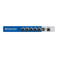
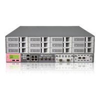
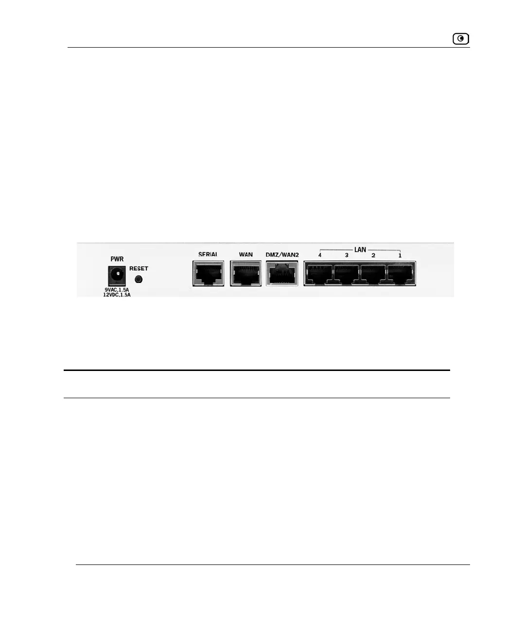
Rear Panel
All physical connections (network and power) are made via the rear panel of your UTM-1
appliance.
The following table lists the UTM-1 Edge X appliance's rear panel elements.
Table 5: UTM-1 Edge X Appliance Rear Panel Elements
Label Description
PWR A power jack used for supplying power to the unit. Connect the supplied power
supply to this jack.
Figure 1: UTM-1 Edge X Appliance Rear Panel